Integration
Introduction
After the Central Pivot and Robotic Leg subassemblies have been assembled and tested, integration of the Central Pivot with the Robotic Leg to become the full Monopod. This section provides instructions on how this may be done.
Motor Cable Preparation
Quantity |
Part |
|---|---|
1pc |
spool of flexible black wire |
6pc |
male gold-tinned 2mm connectors |
1pc |
spool of expandable plastic sleeving |
Instructions:
Cut 6 2.5m long lengths of black wire,
Using a drill or otherwise, twist the black wire together into 2 bundles of 3 wires.
Slowly, inch the expandable plastic sleeving through the bundles of 3 wires until the plastic sleeving covers the entire bundle. Cut the expandable plastic sleeving at the end.
Strip 10cm off the expandable plastic sleeving at both ends of the bundles, so that there is a 10cm length of exposed black wire at both ends of the bundles. Use heat shrink tubing to seal both ends of the plastic sleeving around the wire bundles.
On one end of each bundle, solder on the male gold-tinned connectors. This will be the end of the wire bundle connecting to the Robotic Leg. Insulate by applying heat-shrink tubing around the connectors.
With some solder, tin the wires on the other end of each bundle. This is the end that will be connected to TI BOOSTXL motor driver boards on the Central Pivot, which are in turn connected to a TI Launchpad development board.
Identify which wires in the bundle correspond to which wires on the start and end, with a multimeter. Label the motor phases as A, B, and C.
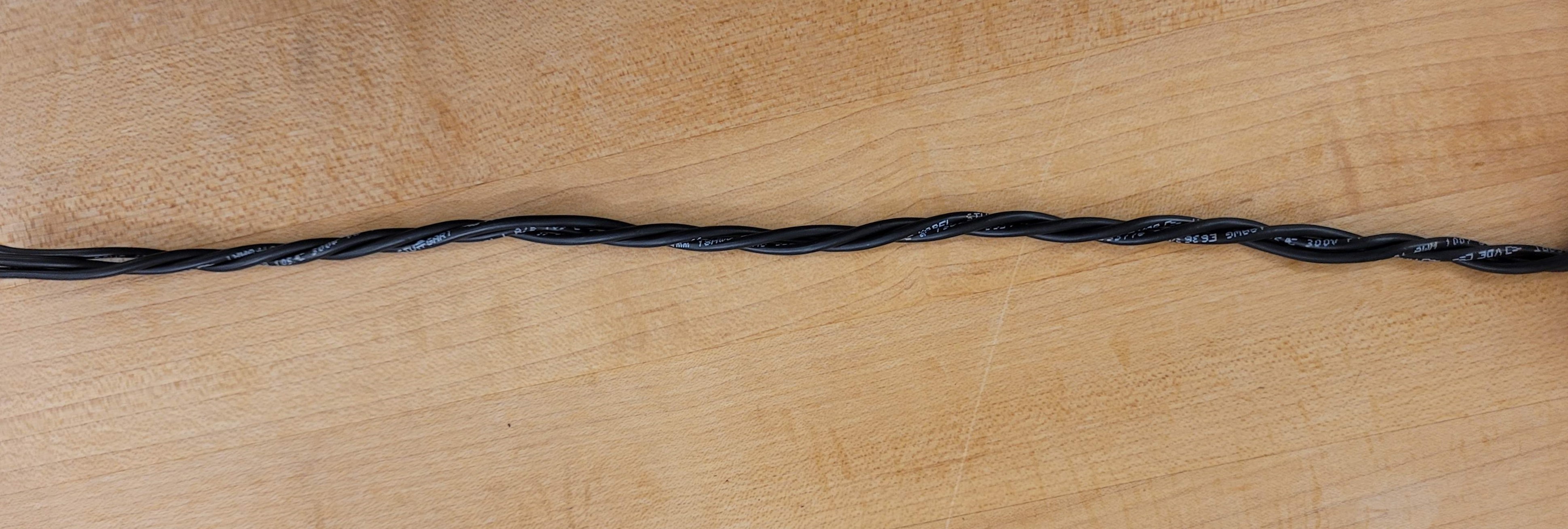
Black wire twisted together in bundles of 3

Expandable plastic sheathing around wire bundles, with heat shrink at the end
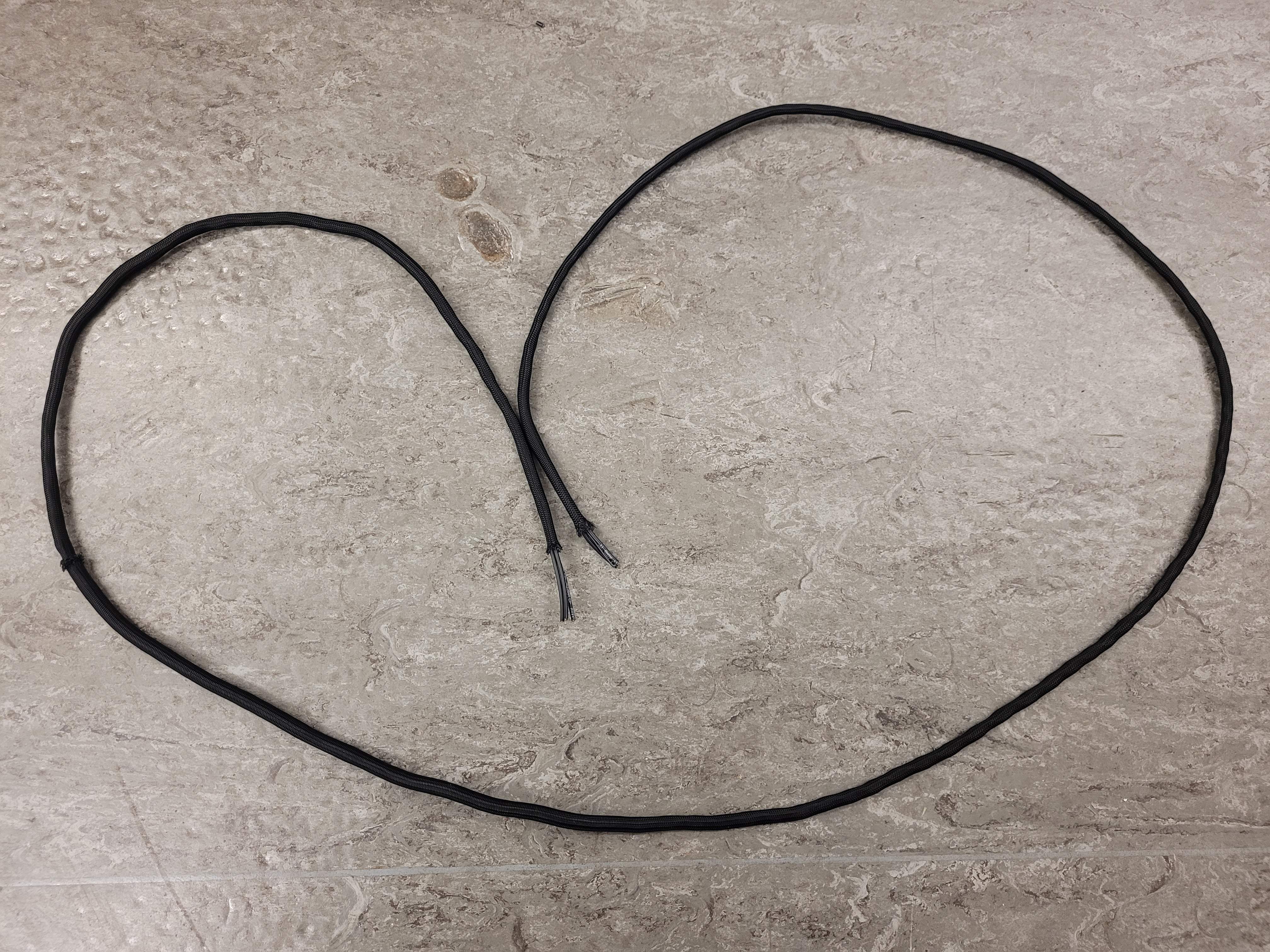
Finished motor 3-phase cable.
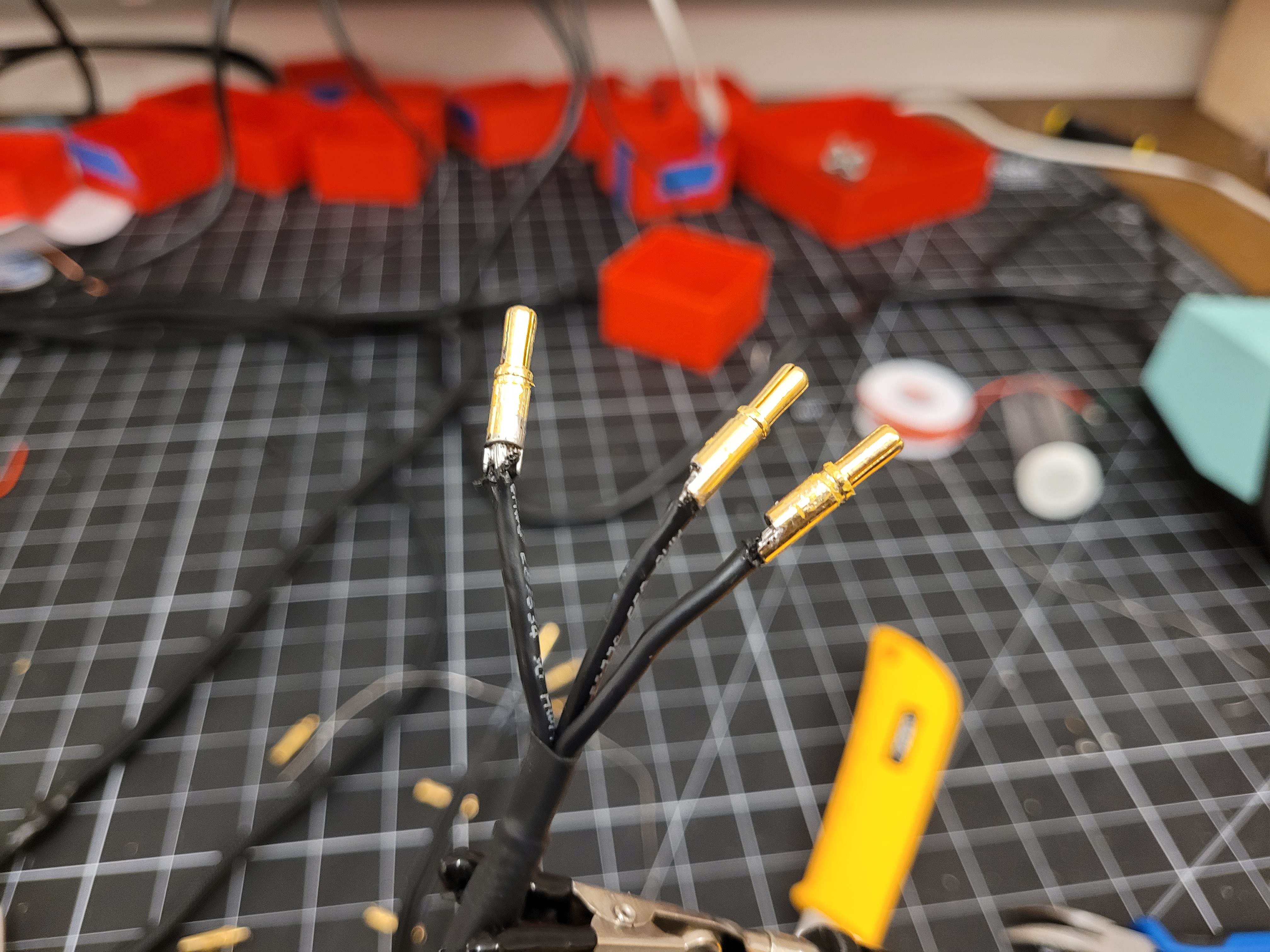
Motor 3-phase cable with male gold-tinned connectors.
There should now be 2 cables to transmit 3-phase motor current from the TI BOOSTXL boards on the Central Pivot to the Robotic Leg, through the long aluminum tube.
Quantity |
Part |
|---|---|
2pc |
2m lengths of 3-wire bundles of black cable |
Encoder Cable Preparation
Quantity |
Part |
|---|---|
1pc |
6’ long female-female cable with 10-pins |
1pc |
1’ long male-male cable with 10-pins |
2pc |
5-pin plastic JST connectors |
10pc |
JST crimp sockets, male |
Instructions:
Cut the 1’ long male-male connector into 2 equal halves.
Screw the halves onto both ends of the long female-female connector.
Strip off some insulation on both ends, exposing 10 wires on each end.
Strip off some insulation off all the wires on both ends.
On both ends, group the 10 wires into 2 groups of 5 wires. Take note of this grouping.
On one end, crimp all 10 wires with the 10 JST sockets, and insert them into 2, 5-pin male JST connectors. This is the end that will connect the encoders to the TI LAUNCHXL boards on the Central Pivot. Take note of which wire color is associated with which pin position and encoder peripheral on the TI board.
On the other end, group the 10 wires into the encoder groupings from the TI board end. Use heat shrink to physically split the 2 groups of wires.
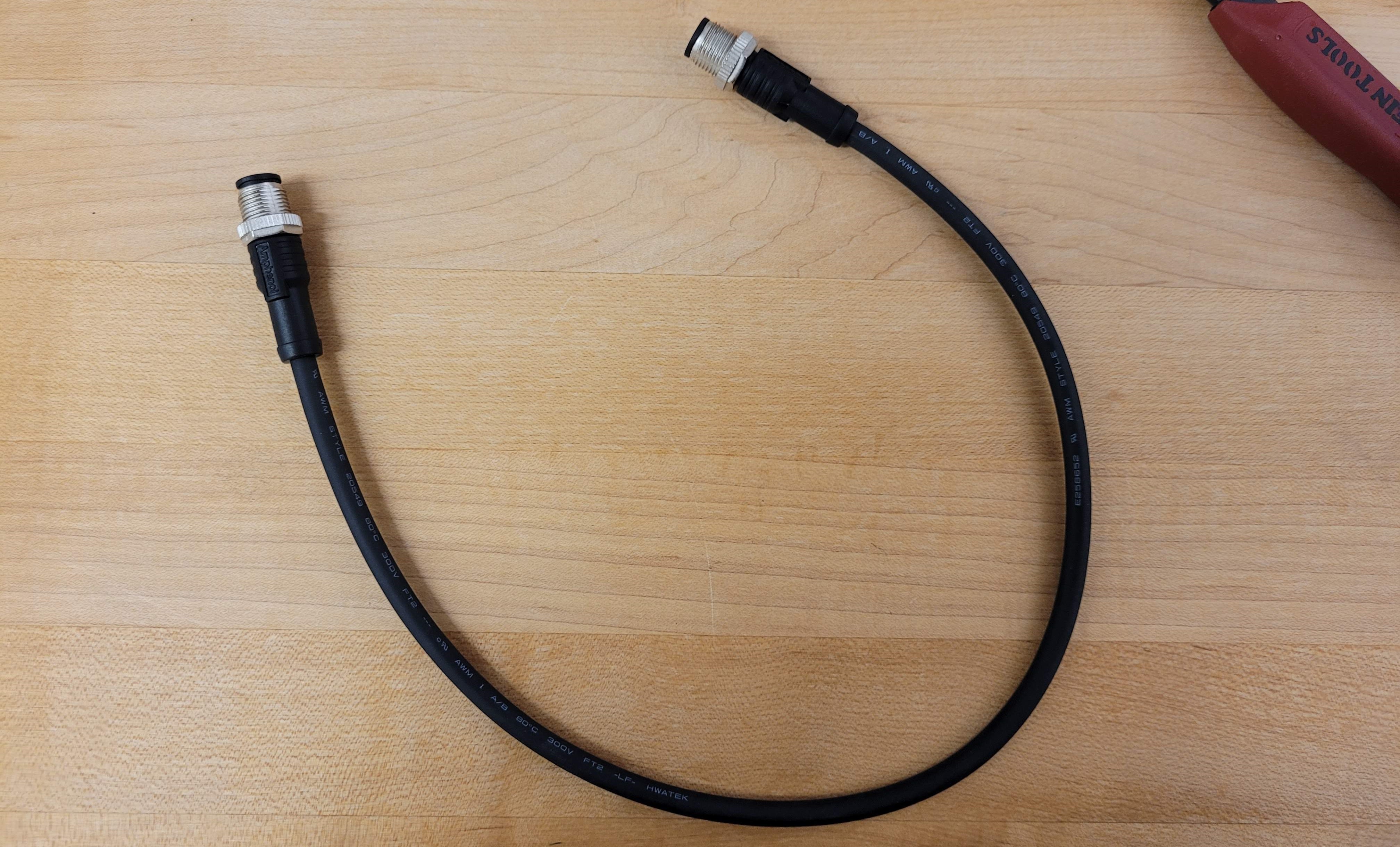
Male-male 10-pin calbe, uncut
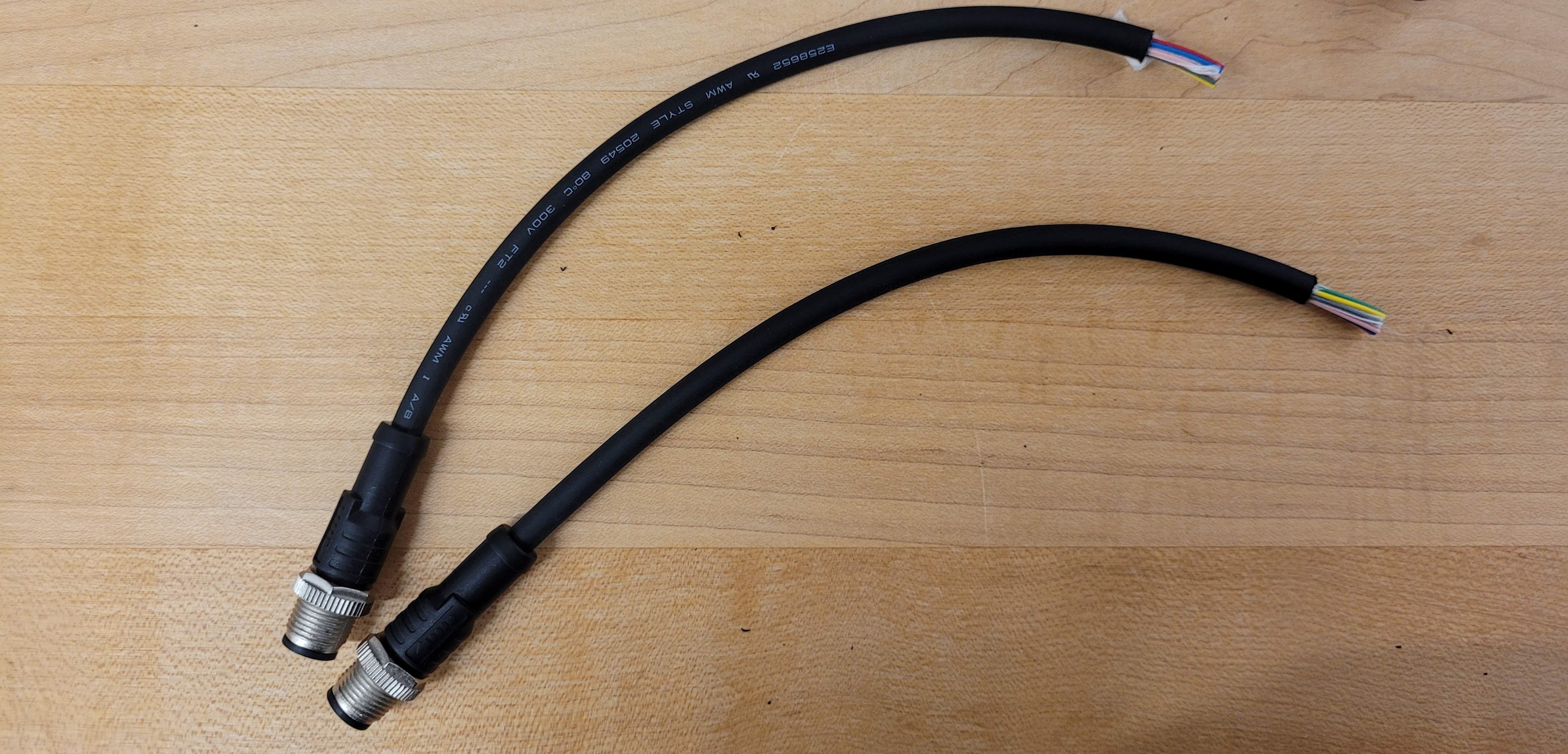
Male-male 10-pin cable, cut
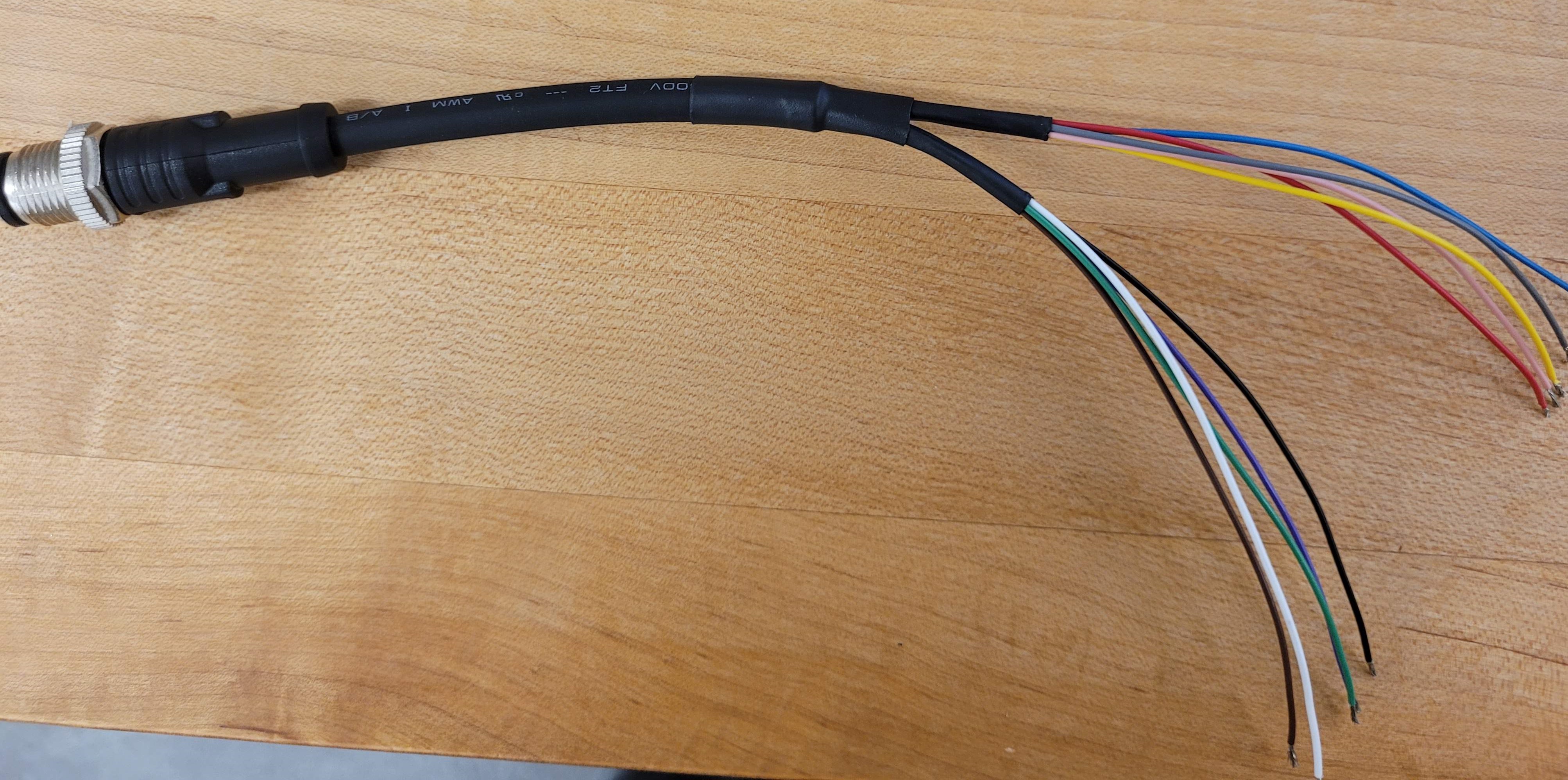
Male-male 10-pin cable, with stripped insulation
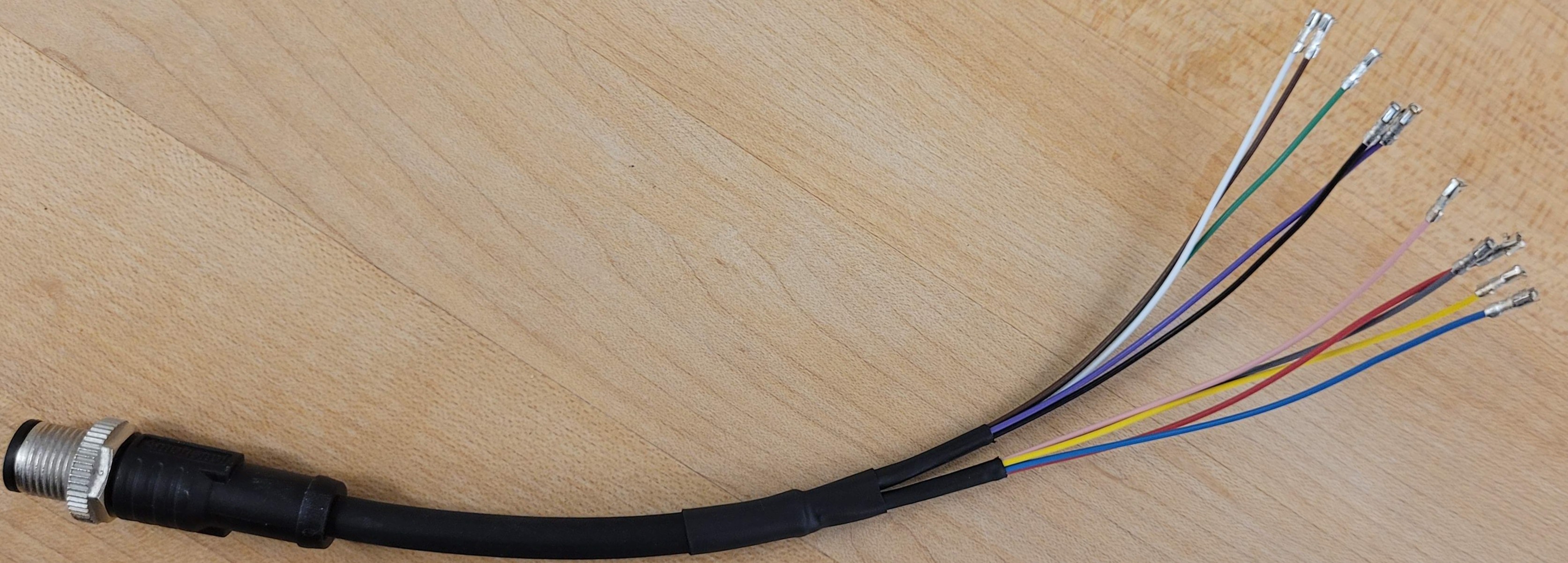
Male-male 10-pin cable, with JST sockets

Male-male 10-pin cable, with male 5-pin JST connectors attached.
There should now be a long cable with 2 JST connectors on one side, and exposed wires on the other side. This cable transmits encoder signals from the Robotic Leg to the TI LAUNCHXL board at the Central Pivot
Quantity |
Part |
|---|---|
1pc |
long cable with 10 wires |
Connections to the Robotic Leg
Quantity |
Part |
|---|---|
1pc |
Robotic Leg from previous assembly processes. |
6pc |
female gold-tinned 2mm connectors |
1pc |
encoder cable from previous assembly processes. |
2pc |
long motor phase cable from previous assembly processes. |
1pc |
spool of expandable plastic sleeving. |
Instructions to connect encoder wires:
Take note of which encoder wires are attached to which pin on which encoder in the Robotic Leg.
Solder the encoder wires to the long encoder cable, paying attention to where each encoder wire should be connected. Apply heat shrink on exposed cable for strain relief, and cover the encoder cables outside the encoder wires with expandable plastic sleeving for additional protection.
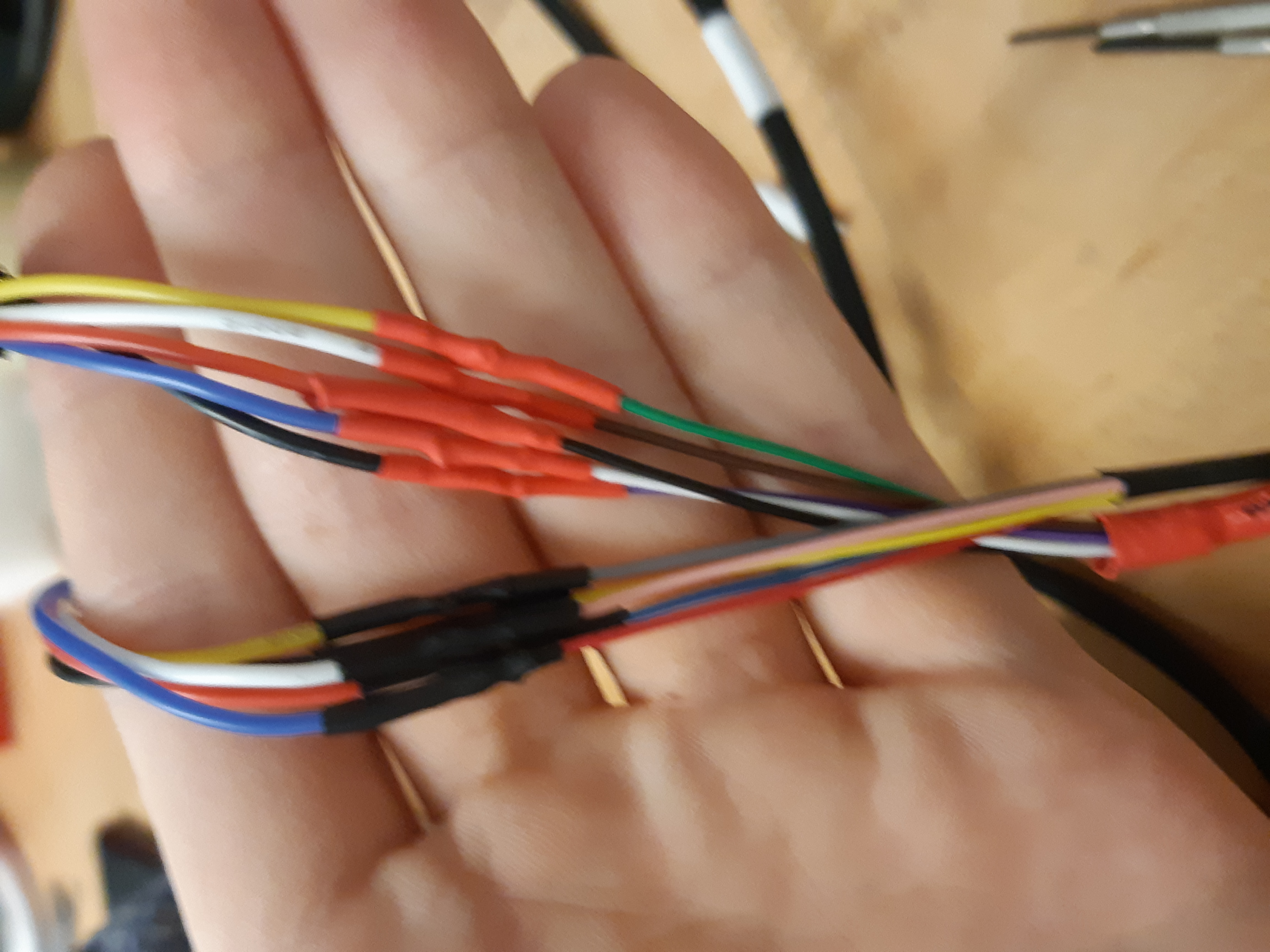
Encoder wires on Robotic Leg connected to the long 10-pin cable. Make sure to cover all wires with a large heat shrink piece for protection.
Instructions to connect motor phase wires:
If the motor phases for each motor are known, label the motor phase wires and the motor number.
Solder on female gold-tinned connectors onto the motor phase wires coming out of the Robotic Leg. Cover the exposed connectors with heat shrink tubing for insulation, and also cover the motor phase wires coming out of the robotic Leg with expandable plastic sleeving for additional protection.
Connect the Robotic Leg motor phase wires with the long motor phase cables.
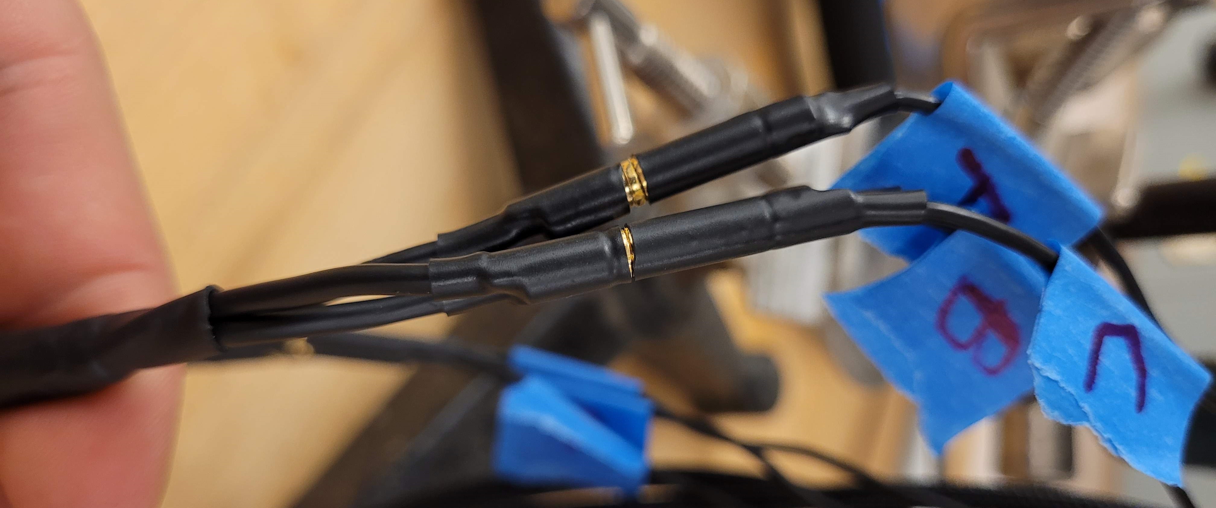
Motor cables from the Robotic Leg are connected to the Motor cables assembled above.

Motor cables and encoder cables from Robotic Leg are connected to the Motor and encoder cables assembled above.
Quantity |
Part |
|---|---|
1pc |
Robotic Leg with extended motor phase and encoder cables. |
Connecting the Robotic Leg and Central Pivot
Quantity |
Part |
|---|---|
1pc |
Robotic Leg from previous assembly processes. |
1pc |
Central Pivot from previous assembly processes. |
Instructions:
Push the lengthened motor phase wires and encoder cable through the long boom such that it emerges on the other end.
Strain relief the connectors on the Central Pivot side.
Connect the motor phase wires and encoder wires to their correct locations on the TI LAUNCHXL and TI BOOSTXL boards on the Central Pivot, using the labels found earlier.
Connect the Robotic Leg to the adapter piece and secure it with bolts and locknuts. Ensure that all of the wires emerging from the Robotic Leg are threaded through the boom.
Secure the TI boards onto a 3D-printed mount on the Central Pivot.
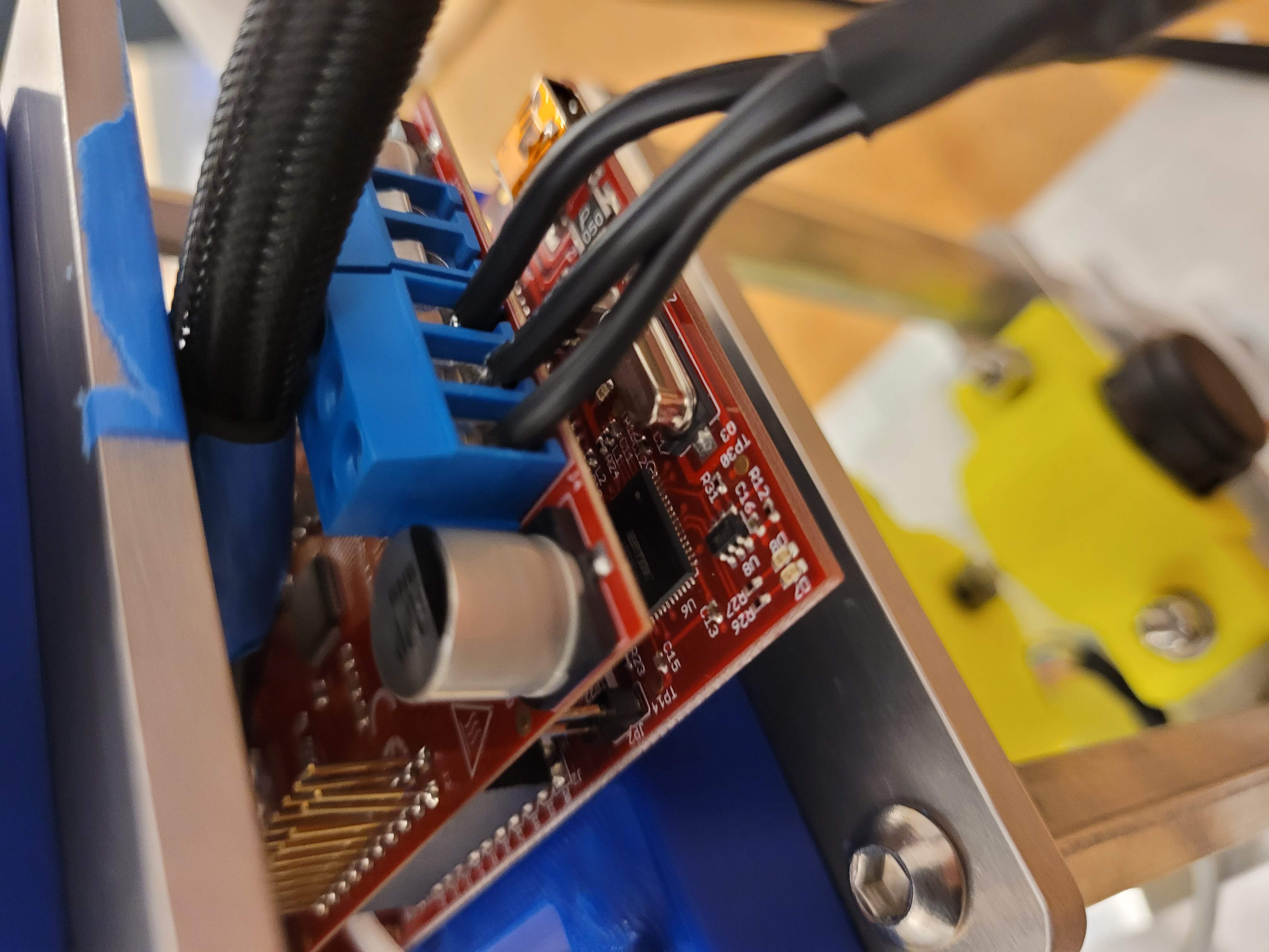
3-phase motor cables connected to the TI boards. Encoder cables should also be connected to the TI boards, using the JST connectors.
Quantity |
Part |
|---|---|
1pc |
Monopod assembly without power connections or CAN connection |
A diagram showing how the encoder and motor cables are wired.
Power Connections
Quantity |
Part |
|---|---|
1pc |
Monopod assembly without power connections or CAN connection |
The TI LAUNCHXL board with the BOOSTXL boards connected to the Robotic Leg can be powered by applying 24V across the power terminals on the BOOSTXL boards, using a power supply. There are many ways to set up this power connection, but we used the following setup:

Cut 2 BNC connectors, and strip off the ends
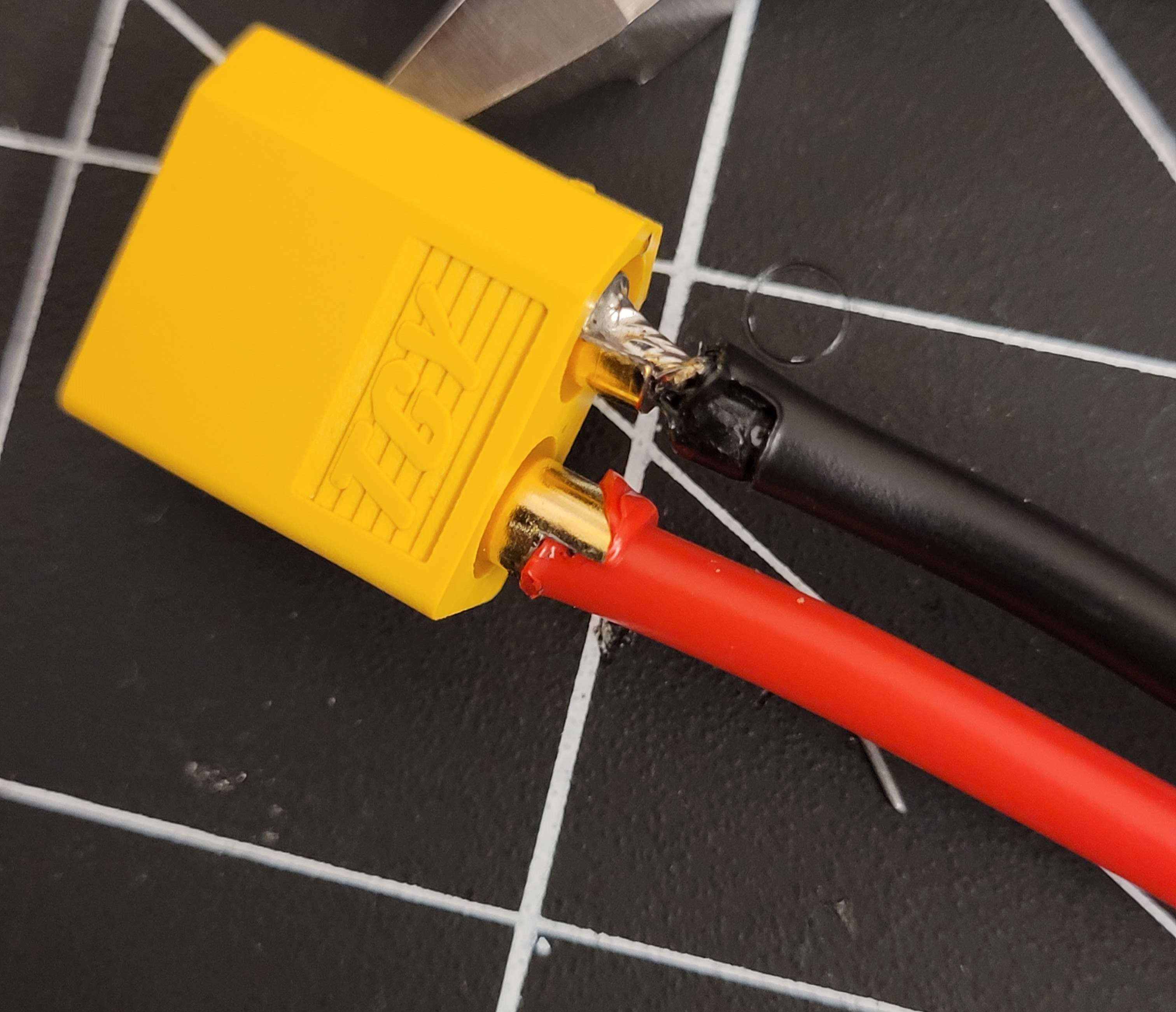
Solder on a 2-pin male connector.

Apply heat shrink around each individual wire.

Apply heat shrink around both wires. The BNC connectors will connect to a power supply.

Cut 2 lengths of black wire and 2 lengths of red wire ~50cm long, and solder one end to a female 2-pin connector. The other ends will connect to the power terminals of each BOOSTXL board.
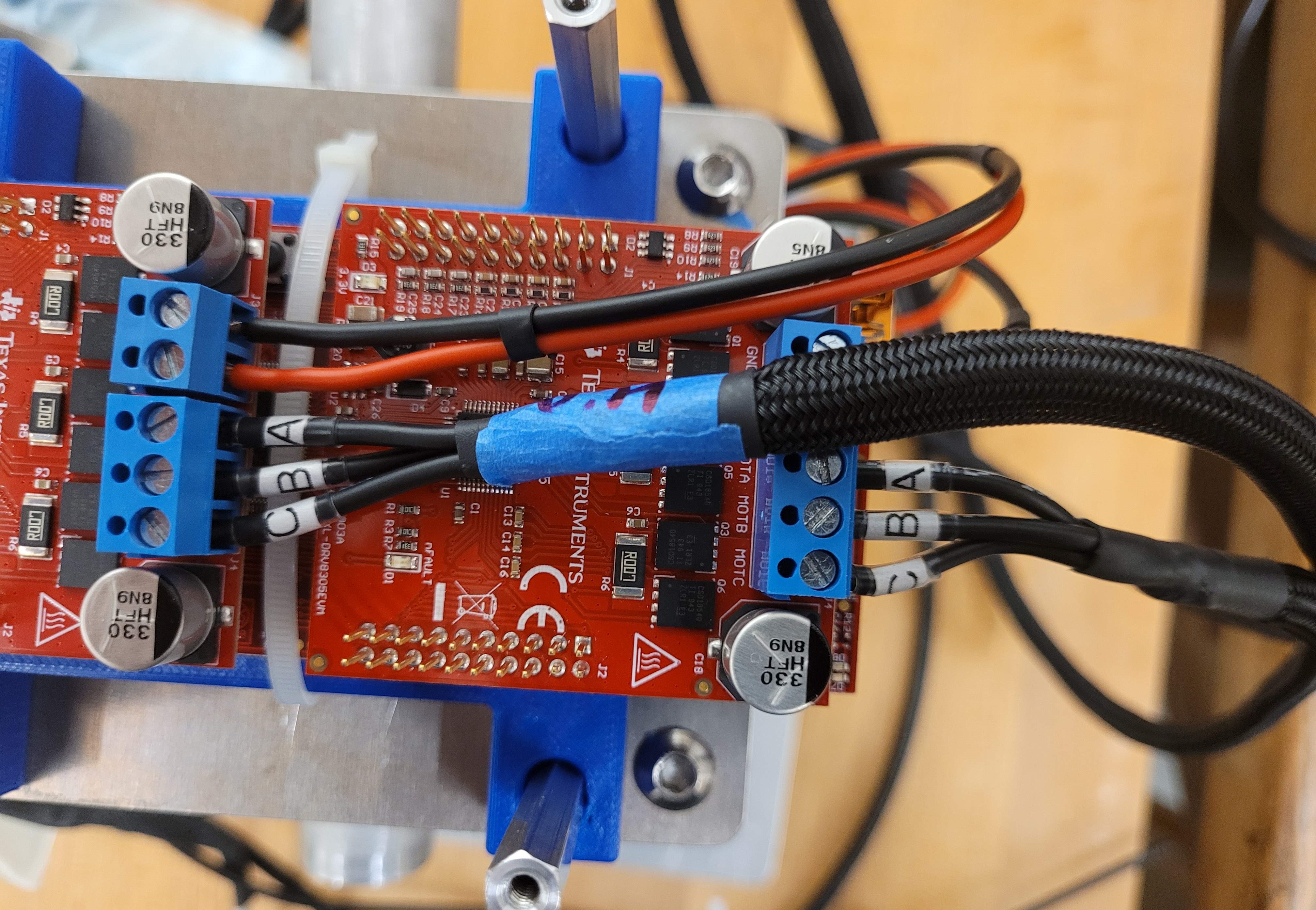
Power terminal connection to the BOOSTXL boards.
Connect the male and female 2-pin connectors to complete the power connection for the Robotic Leg
The TI LAUNCHXL board with the Central Pivot encoders attached can be powered by applying 3.3V across the 3.3V and Ground pins on the TI LAUNCHXL board. This can be done by connecting the 3.3V pins of both TI LAUNCHXL boards together, and the Ground pins of both TI LAUNCHXL boards together, with individual wires.
Quantity |
Part |
|---|---|
1pc |
Monopod assembly without CAN connection |
A diagram showing how the power electronics are wired.
CAN Connections
Quantity |
Part |
|---|---|
1pc |
Monopod assembly without CAN connection |
Instructions to connect TI LAUNCXL boards to CAN:
The TI LAUNCHXL boards have header pins for CAN. A Y-shaped connector between the TI LAUNCHXL boards, and a CAN-to-USB device can be made with 3-pin cabling.
The CAN-to-USB device is then connected to a computer, completing the setup of the Monopod.
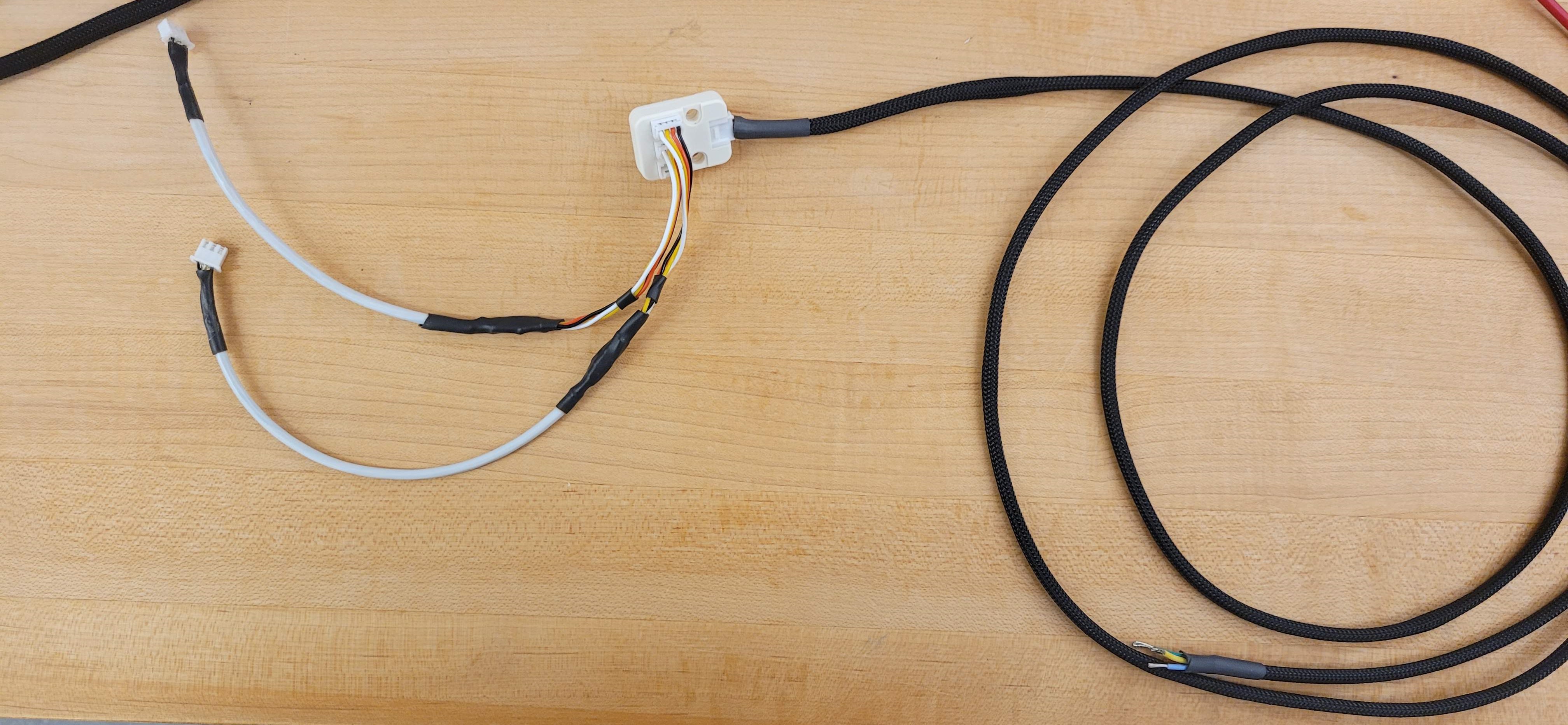
A Y-shaped connector between the TI LAUNCHXL boards and the CAN-to-USB device.
Quantity |
Part |
|---|---|
1pc |
Complete Monopod Assembly |
A diagram showing how the CAN communication buses are wired.
Conclusion
Now, the Central Pivot and the Robotic Leg are connected together, and both are connected to a power supply and to a computer via CAN. Integration between the Central Pivot and the Robotic Leg is complete, and so the Monopod is complete and can be tested.