Leg Instructions
Introduction
The Robotic Leg is part of the complete Monopod, and the build instructions follows closely from the build instructions provided by the Open Dynamic Robot Initiative. However, several clarifying instructions have been added here to aid construction.
Before starting assembly, ensure that all parts in the Bill of Materials for the Robotic Leg have arrived.
About ODRI
The Open Dynamic Robot Initiative 1 is a project by the Max Planck Institute for Intelligent Systems to create a low cost, open source, robotics platform for researchers to experiment with legged actuation. ODRI’s robotic platform consists of modular actuators which can be assembled in various configurations to serve different purposes.
This project uses 2 such modular actuators, assembled into a 2-jointed Robotic Leg. Several modifications from the base design were made to facilitate connection with the Central Pivot assembly, but most of the assembly instructions remain unchanged.
The ODRI-provided instructions are found here:
This section provides additional commentary and troubleshooting advice.
3D Printing
Instructions
The Robotic Leg requires the following STL parts to be printed:
Quantity |
Part Name |
|---|---|
1 |
|
1 |
|
1 |
|
1 |
|
1 |
|
2 |
|
2 |
|
2 |
|
4 |
|
1 |
|
1 |
|
1 |
|
1 |
|
1 |
|
1 |
|
1 |
ODRI has the following recommendations for 3D printing. Adapt them as necessary for the parts we have.
Our team recommends the SLS process with Nylon 12 material to print all the parts. Our team recommends not using inexpensive FDM printers with the commonly available PLA material - some FDM printers do not have sufficient precision, and this will cause problems when fitting parts together. The PLA material also has a low glass transition temperature, which constitutes a risk of part deformation under high pressures or temperatures.
The STL files provided in our BOM have their holes and features offset by 0.2mm of radius. This ensures that all bearings and 3D printed parts will fit into each other with minimal application of force. 3D printers of inferior quality often overfill or underfill these features, therefore this modification to the STL files is necessary. STEP files without this feature modification are also provided in the BOM.
Preparation
ODRI has the following instructions for 3D printed parts preparation. Adapt them as necessary for the parts we have.
Suggestions:
If the 3D printed parts have their features adjusted as above, then the further modification of part dimensions described by ODRI are no longer required, although some drilling of M2.5 and M3 holes to size might still be necessary. When that has been completed, the described tapping of holes for M3 screws, and M2.5 and M3 helicoils can be started.
Our team recommends printing dummy parts to practise tapping and helicoil insertion, before applying this procedure on the real parts. This is important because an incorrectly inserted helicoil could cause an actuator shell to not close properly.
The bearings now might be a bit too loose for their bearing seats. If that is the case, then apply some thin tape around the rim of the bearings until it is a snug fit.

Upper Leg Base Shell, after helicoil insertion and threading. Do the same thing for the Static Hip Base Shell.

Upper Leg Cover Shell, after helicoil insertion and threading. Do the same thing for the Static Hip Cover Shell.

Upper Leg Base Shell, with bearings inserted.

Upper Leg Cover Shell, with bearings inserted.
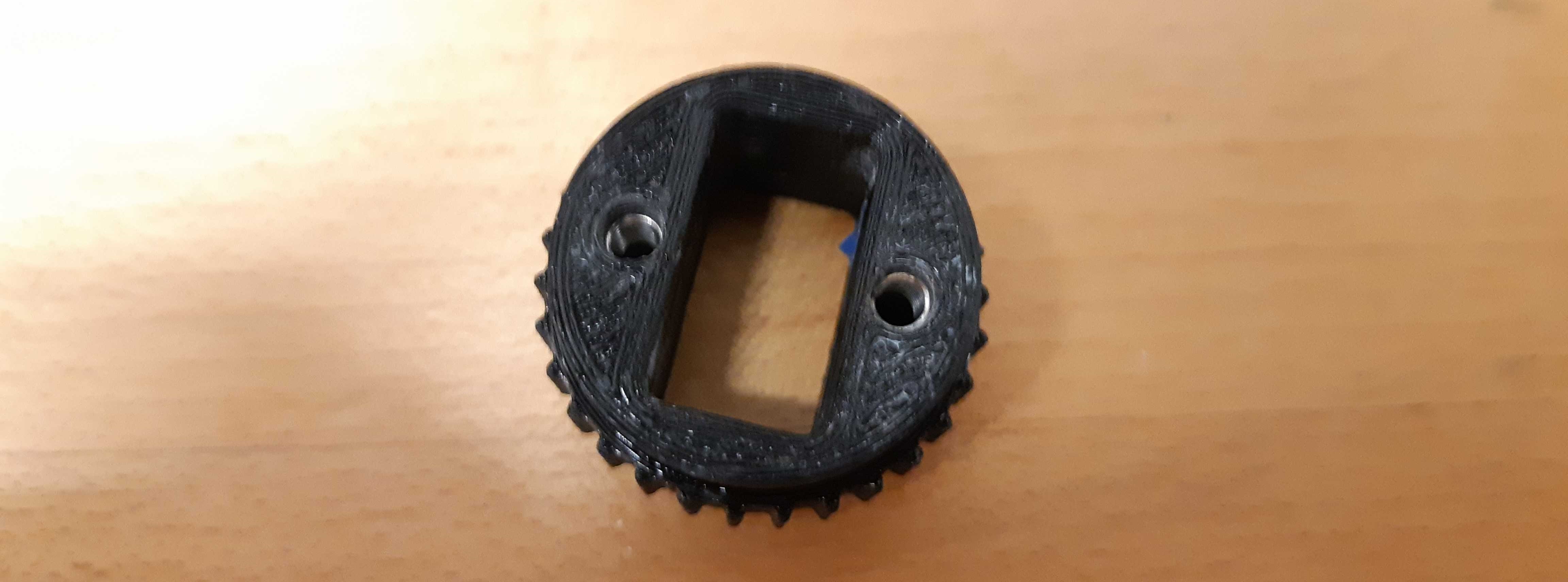
Output Pulley, after helicoil insertion. Make 2 of these.
Motor Shaft
ODRI has the following instructions for the motor shaft preparation.
Encoder Disassembly: Process to disassemble an encoder to get the encoder code wheel and the encoder electronics.
Machined Parts Preparation: Instructions to get the necessary machined parts.
Motor Shaft Preparation: Process to create a motor shaft assembly with the encoder code wheel
Suggestions:
The motor shaft preparation steps are quite difficult to follow. The machined timing belt pulleys are difficult and/or expensive to get and even more difficult to machine, and cutting the encoder disc down to size is also a very difficult and delicate process. The motor shaft preparation guide also requires a lot of finessing to get right.
Instead, our team and ODRI, recommends buying a pre-built motor shaft here: PWB Encoders ODRI Kit. Our team recommends buying this early, and getting extras, because the lead time for this product can get quite long for North American users.
Encoder
ODRI has the following instructions to prepare the encoders. Follow these, but disregard the instructions to crimp the Hirose connectors, as we will be using different connectors.
Suggestions:
Measure out 30-50cm for each encoder wire.
Again, do not follow the instructions given for the Hirose connectors.
Motor
ODRI has the following instructions to prepare the motors:
Suggestions:
Do not forget that the motor shaft is connected to the motor rotor by 2 threaded inserts. Make sure that those are removed before attempting to separate the motor shaft from the motor rotor, otherwise you risk shearing parts of the threaded insert, or the motor shaft.
Remember that when the BLDC motors were bought from the store, they came with a brass spacer. Make sure to keep these spacers safely, they are needed in the leg actuator assembly process.
Center Pulley
ODRI has the following instructions to prepare the center pulley
Suggestions:
It is important to ensure that the machined timing belt pulley is centered on the 3D-printed part and is vertical. Otherwise, the timing belt will not mesh properly with it. We recommend filing down the side of the machined pulley that will be pushed into the 3D-printed part to reduce the amount of force needed to push the two parts together using an arbor press.
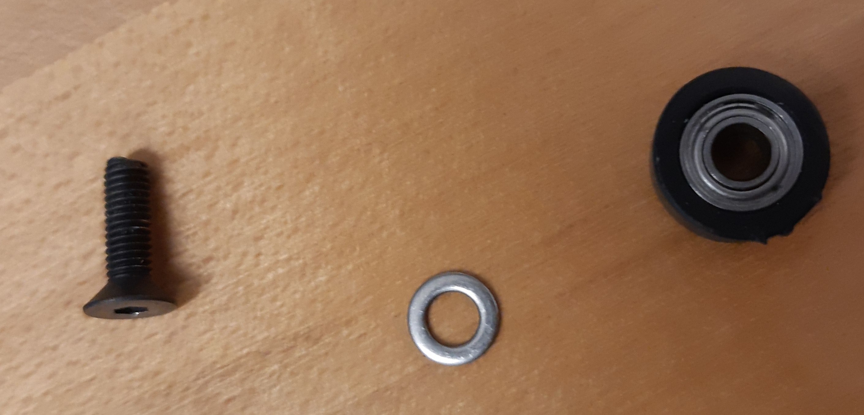
3D-printed roller with bearing inserted, with spacer and screw
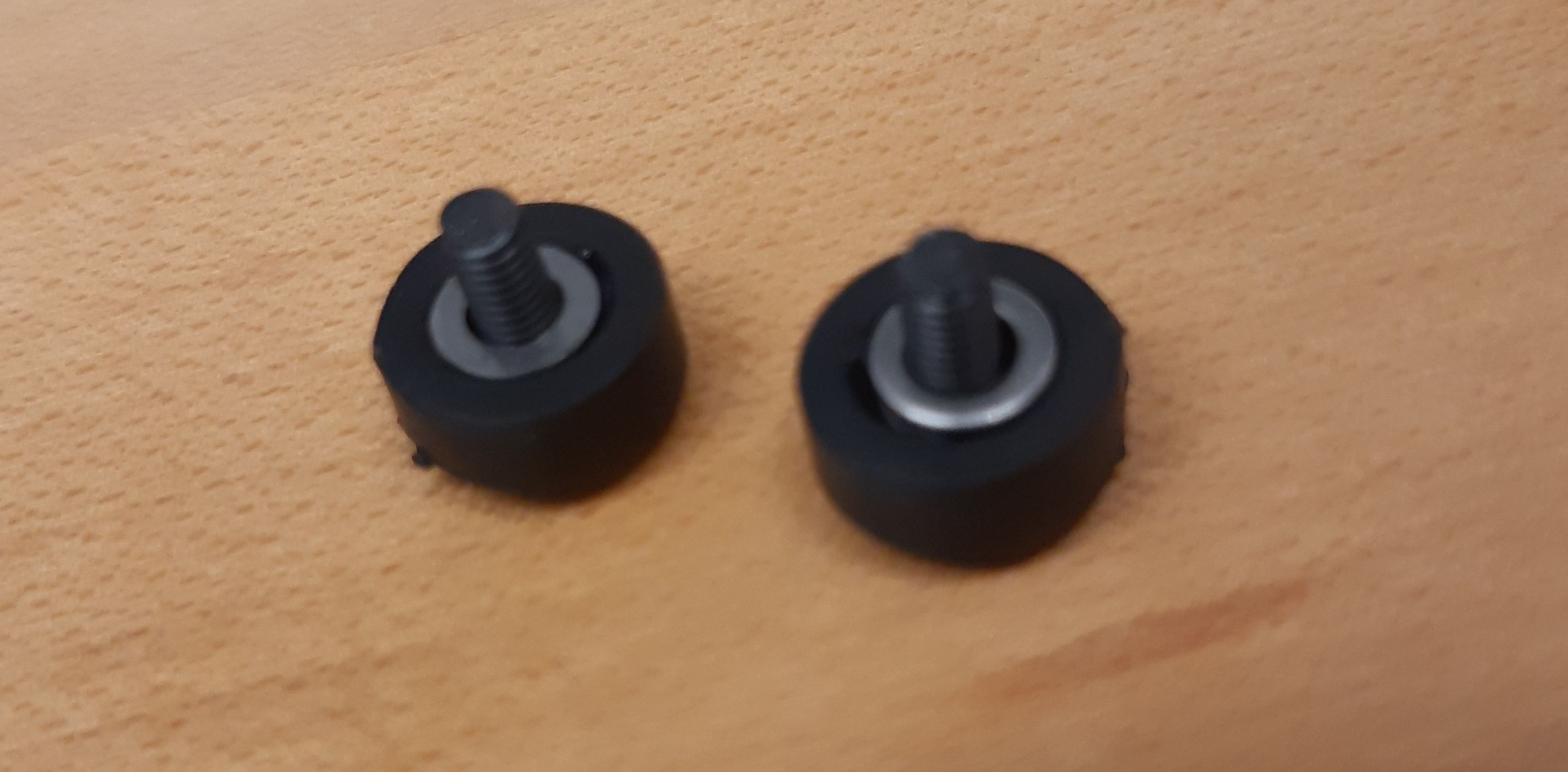
Completed rollers.
Final Assembly
At this point, the subcomponents have all been assembled and it is possible to put together the actuator.
ODRI has the following instructions for the final assembly process.

Upper Leg Base Cover with encoder inserted
The assembly process is similar for both the “hip” and “leg” actuator.
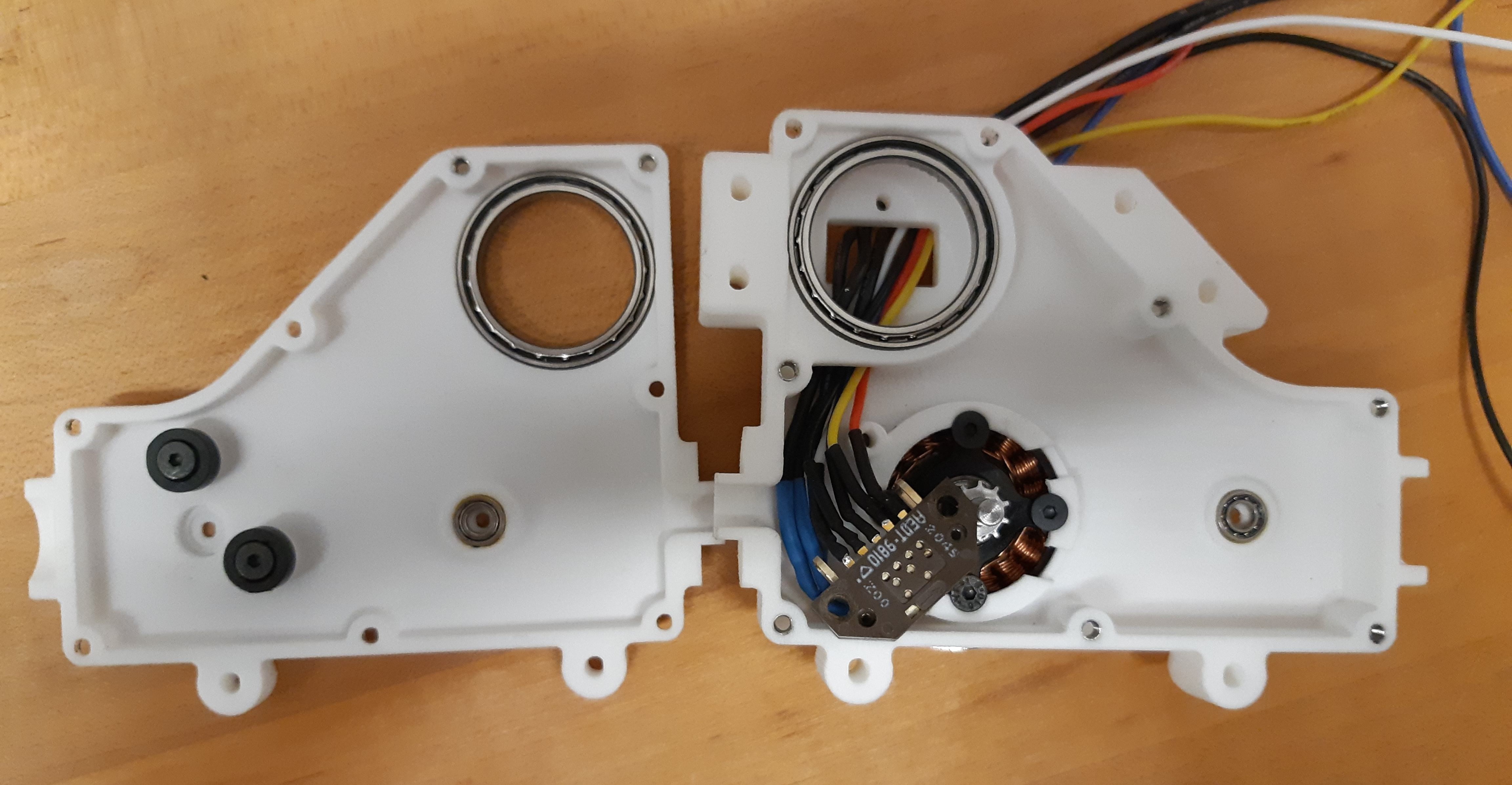
Hip base and cover shell, with encoder inserted.
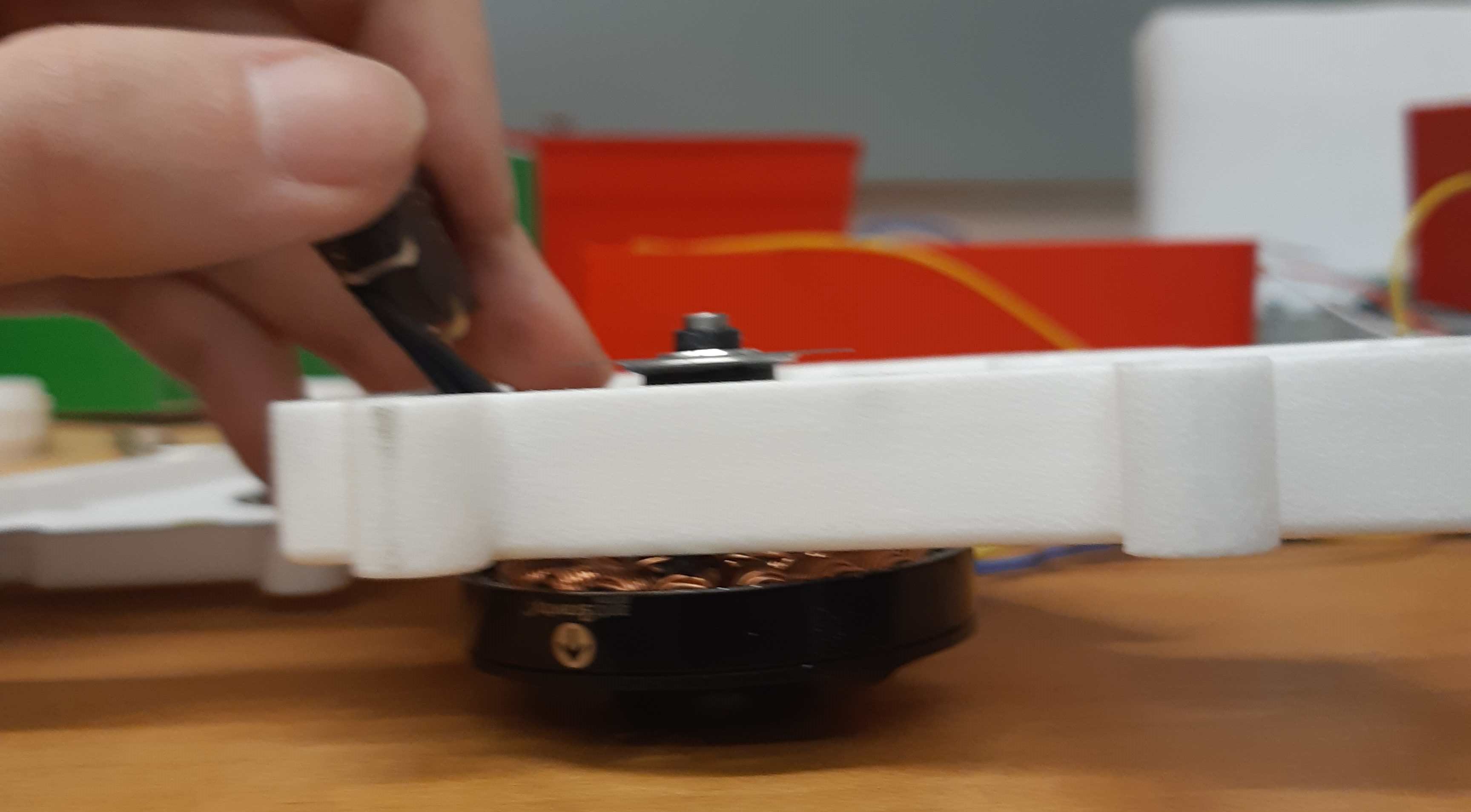
Encoder disc inserted into the motor shaft, on the Hip base shell
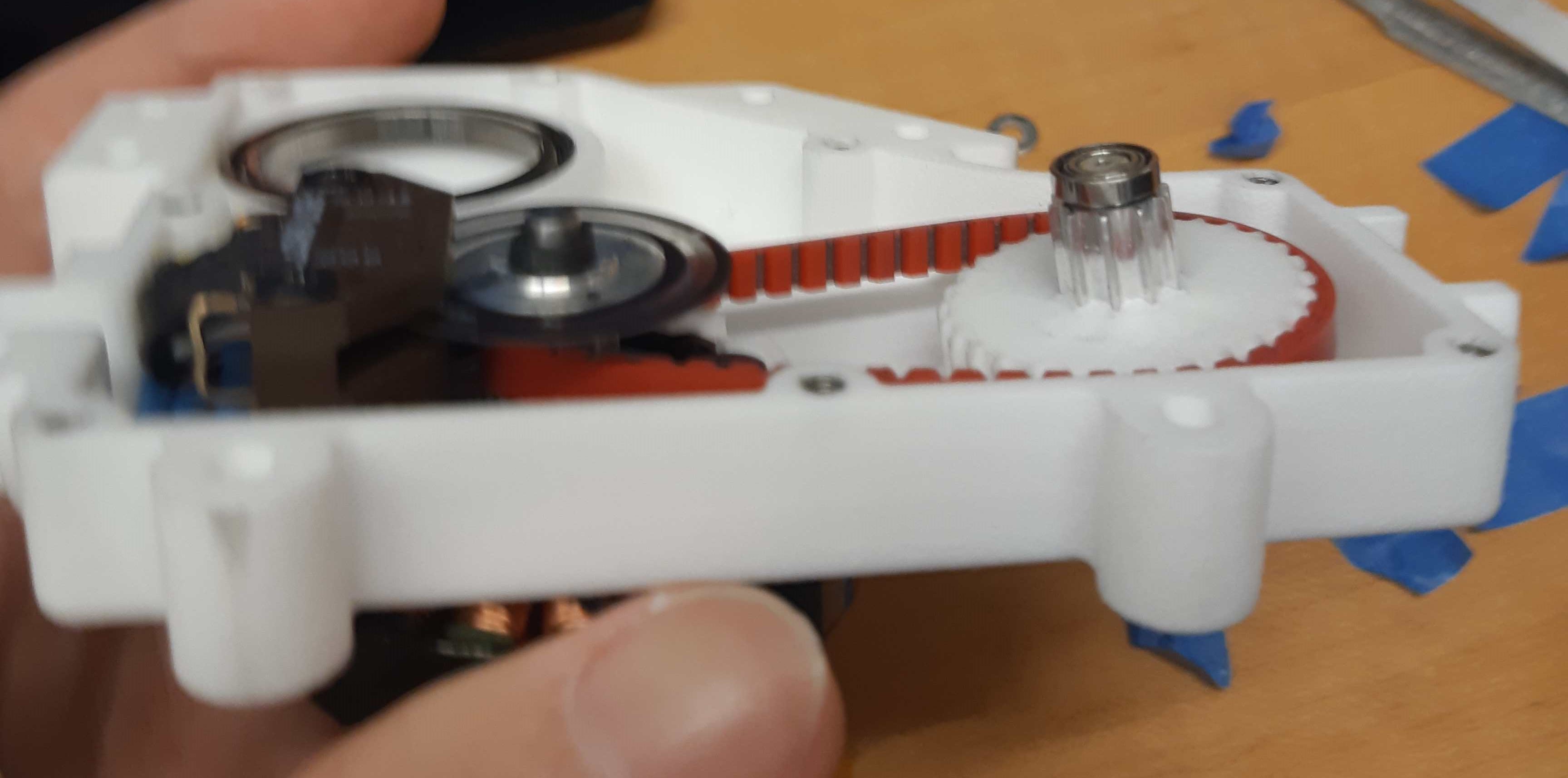
Partially assembled hip actuator.
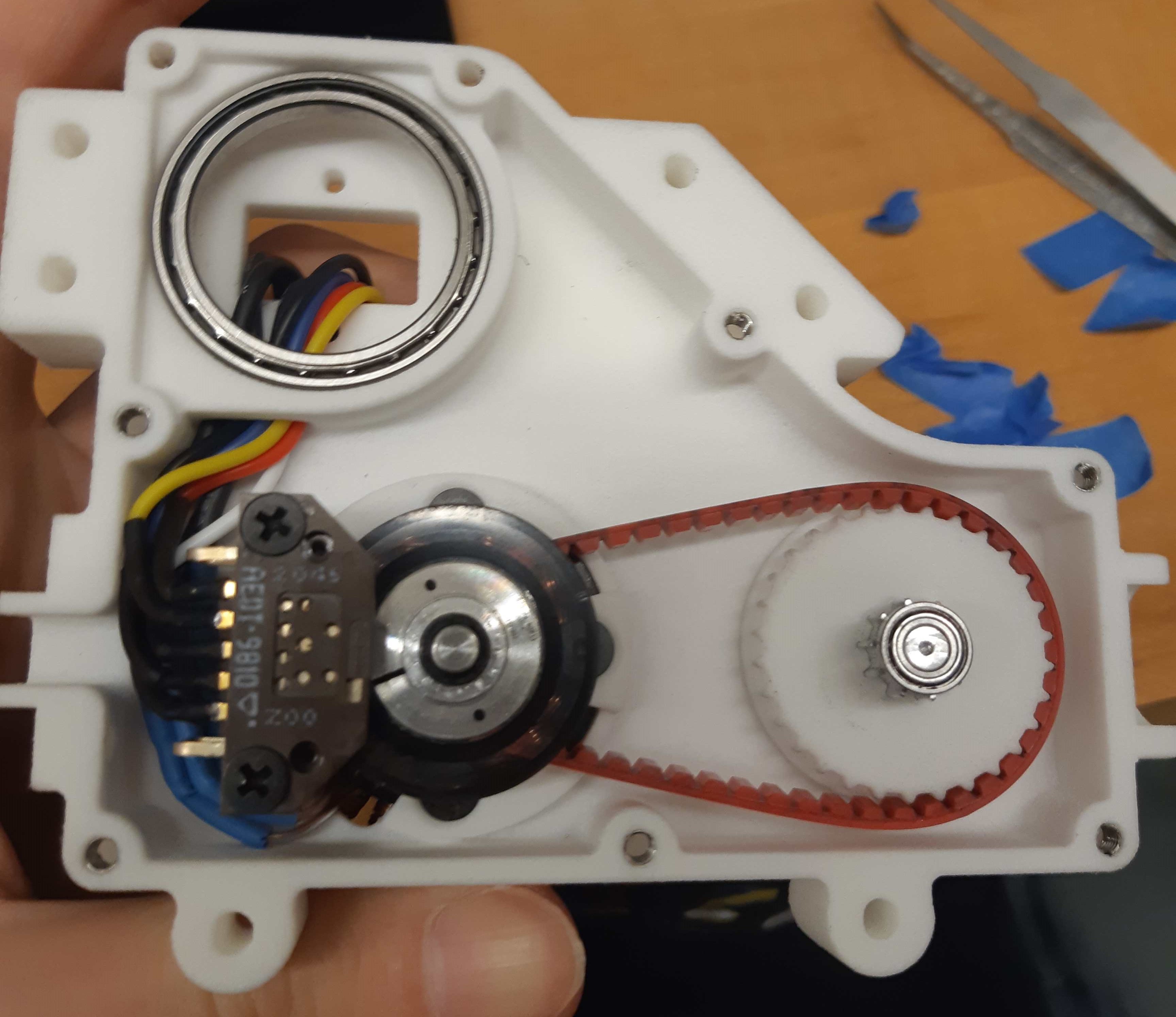
Another view of a partially assembled hip actuator.
Suggestions:
Before closing the shells of the leg or hip actuators, ensure that the encoder disc, attached to the motor shaft, is spinning freely and is not being scratched by the encoder reader or interfering with any other part. If they are interfering, you must disassemble the encoder assembly again and correct for any misalignments which may have caused the encoder disc to not spin freely. The tolerance is very tight; the encoder wheel must spin within a ~3mm air space, so be very careful.
Before attaching the motors to the shell, make sure that the motor stator, rotor and shaft, as well as the shell, are free of any magnetic and non-magnetic debris. Magnetic debris can be removed with strong tape.
Make sure that the spinning 3D printed parts are clean of print artifacts, otherwise they might interfere with non-spinning parts and cause friction. Protect all the bearings from debris, and don’t apply a lot of axial force on them, otherwise the bearings might have more friction than expected. If possible, use shielded bearings instead of open bearings - this is totally worth it, even though the open bearings are cheaper.
Conclusion
At the end of this section, there should be a single “hip” actuator, and a single “leg” actuator assembled. Do not attach them together yet, as testing requires both actuators to be seperated first.
- 1
F. Grimminger, A. Meduri, M. Khadiv, J. Viereck, M. Wüthrich, M. Naveau, V. Berenz, S. Heim, F. Widmaier, T. Flayols, J. Fiene, A. Badri-Spröwitz, and L. Righetti. An open torque-controlled modular robot architecture for legged locomotion research. IEEE Robotics and Automation Letters, 5(2):3650–3657, 2020. doi:10.1109/LRA.2020.2976639.