Central Pivot Instructions
Introduction
The Central Pivot is part of the complete Monopod, and its purpose is to constrain the Robotic Leg in a 2D plane. Unlike the Robotic Leg, however, the Central Pivot is an original design from OpenSim2Real. The following steps should be done in order, after all parts have arrived.
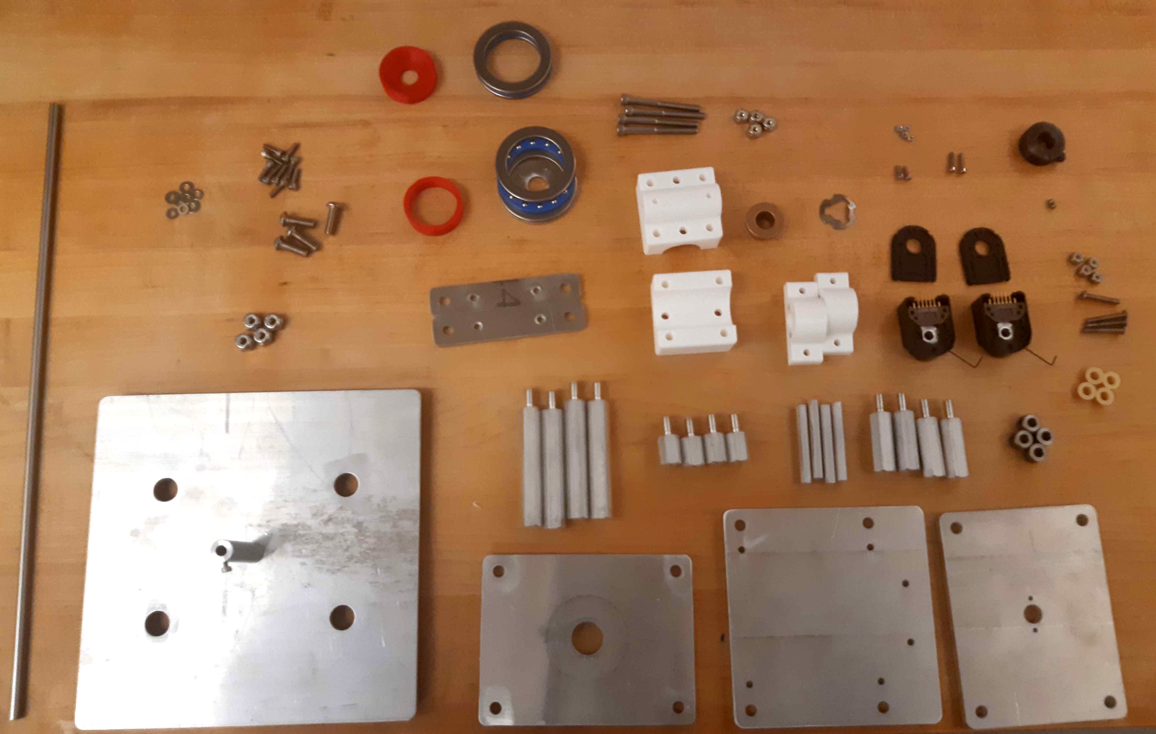
Consumables for the Central Pivot.
Waterjet Parts Preparation
If that has not been done already, waterjet the required parts in the BOM out of quarter-inch aluminum:
Quantity |
Waterjet Aluminum Part Link |
|---|---|
2pc |
|
1pc |
|
1pc |
|
1pc |
|
1pc |
|
1pc |
|
1pc |
Deburr all the edges of the waterjet cut pieces to avoid getting cut by sharp edges.
3D Printed Parts Preparation
If not done already, 3D print the required parts in the BOM.
Quantity |
3D Printed Parts |
|---|---|
2pc |
|
1pc |
|
1pc |
|
1pc |
|
1pc |
|
1pc |
|
1pc |
Remove all support material at this stage of preparation.
Axle Mount Preparation
Quantity |
Part |
|---|---|
2pc |
3D printed Axle Mount pieces. |
2pc |
Aluminum Axle Holder pieces. |
4pc |
M2.5x6.3mm helicoils. |
4pc |
sleeve bearing for 6mm shaft, 4mm length. |
4pc |
6-32 bolts, 1” long. |
4pc |
6-32 locknuts |
Using a M2.5 helicoil tap, tap the 2 small holes on the Axle Mounts. Using a M2.5 helicoil insertion tool, insert M2.5 helicoils into these tapped holes. Using a M2.5 helicoil tang breakoff tool, break off the tangs inside the M2.5 helicoils. Do this for both Axle Mounts.
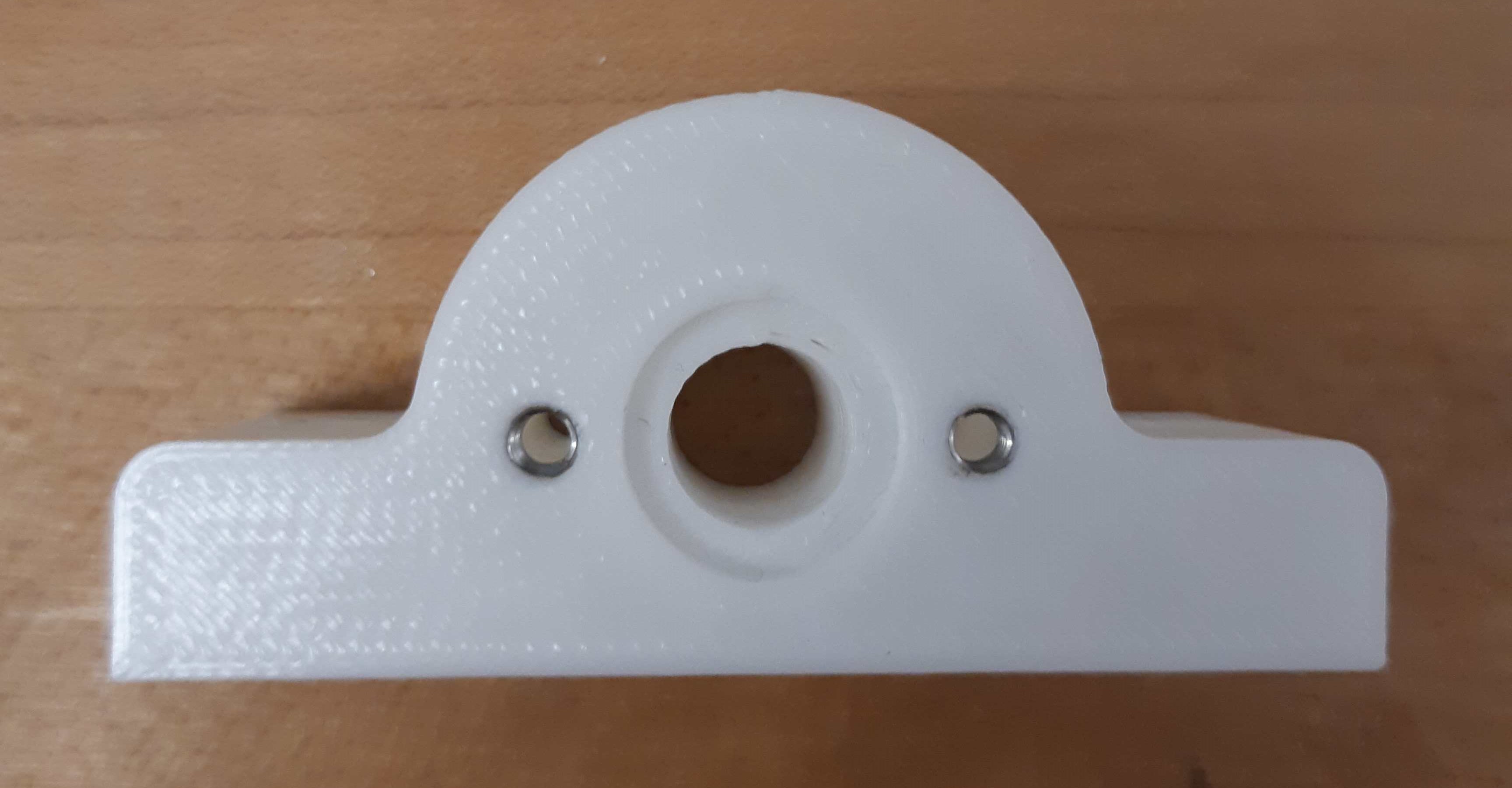
Axle Mount with helicoils inserted.
Insert one sleeve bearing into each end of each 3D printed Axle Mount. Repeat for both Axle Mounts so that 4 sleeve bearings are used in total.
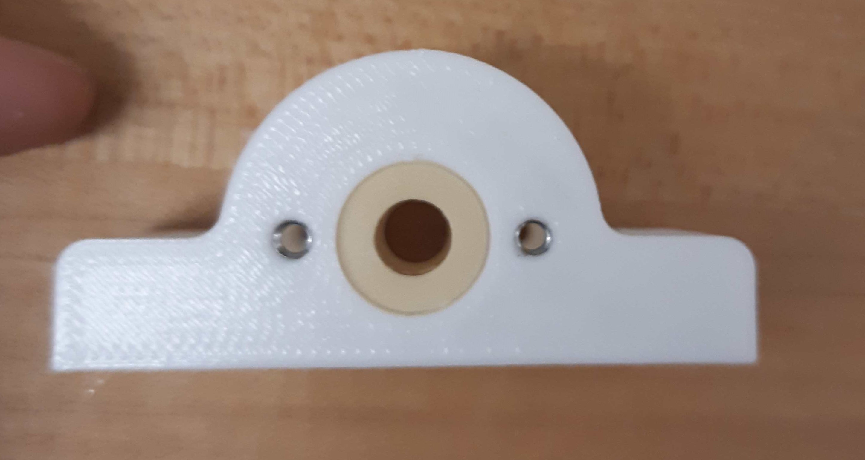
Axle Mount with sleeve bearings mounted.
Finally, secure the 3D printed shaft holders to the Axle Holder aluminum plates with 6-32 bolts and nuts.

3D printed Axle Mounts mounted to the aluminum Axle Holders.
Quantity |
Part |
|---|---|
2pc |
Completed Axle Mounts |
Baseplate Preparation
Quantity |
Part |
|---|---|
1pc |
Aluminum “Baseplate” |
1pc |
1/4”-20 screw with 1” length, flat head |
1pc |
Aluminum Unthreaded Spacer 1/2” OD, 2” Long, for 1/4” Screw Size |
In the center hole of the baseplate, drill a countersink for a 1/4” screw. Tap the hole for a 1/4” screw. Test insert a 1/4” screw - a good fit should have the bolt sit flush so that the baseplate could lie flat on a table.
Once a good fit on the 1/4” screw has been determined, loctite the screw onto the baseplate.
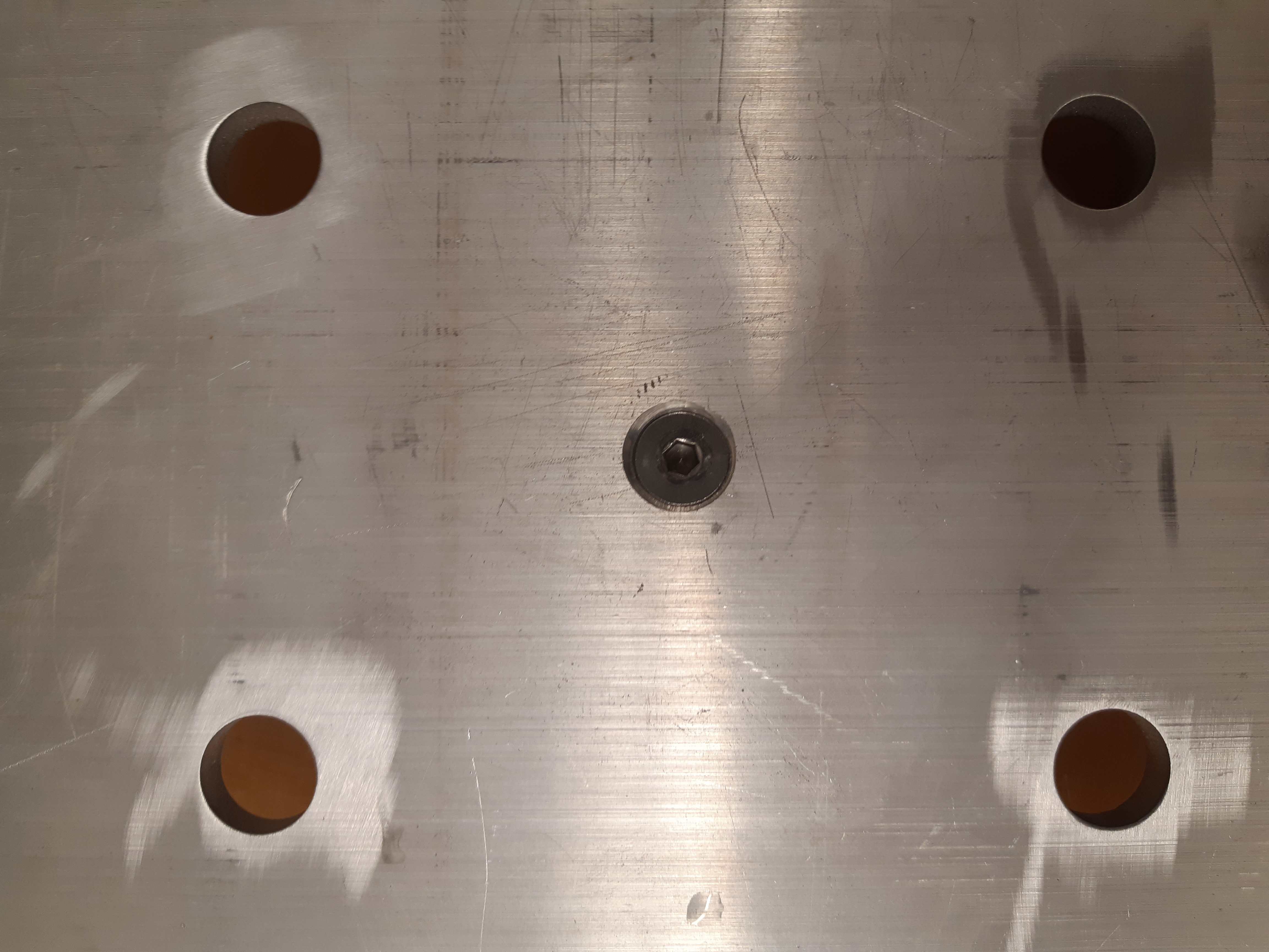
Screw on the baseplate aluminum piece. Note that the flat-head screw is countersunk.
Screw the aluminum unthreaded spacer onto the 1/4” screw protruding out of the baseplate. Ensure there is no gap between the standoff and the baseplate. Optionally, a small hole can be drilled and tapped into the side of the aluminum spacer, and tapped with a M2.5 thread. This allows an M2.5 set screw to be inserted to secure any shaft which enters the hole.
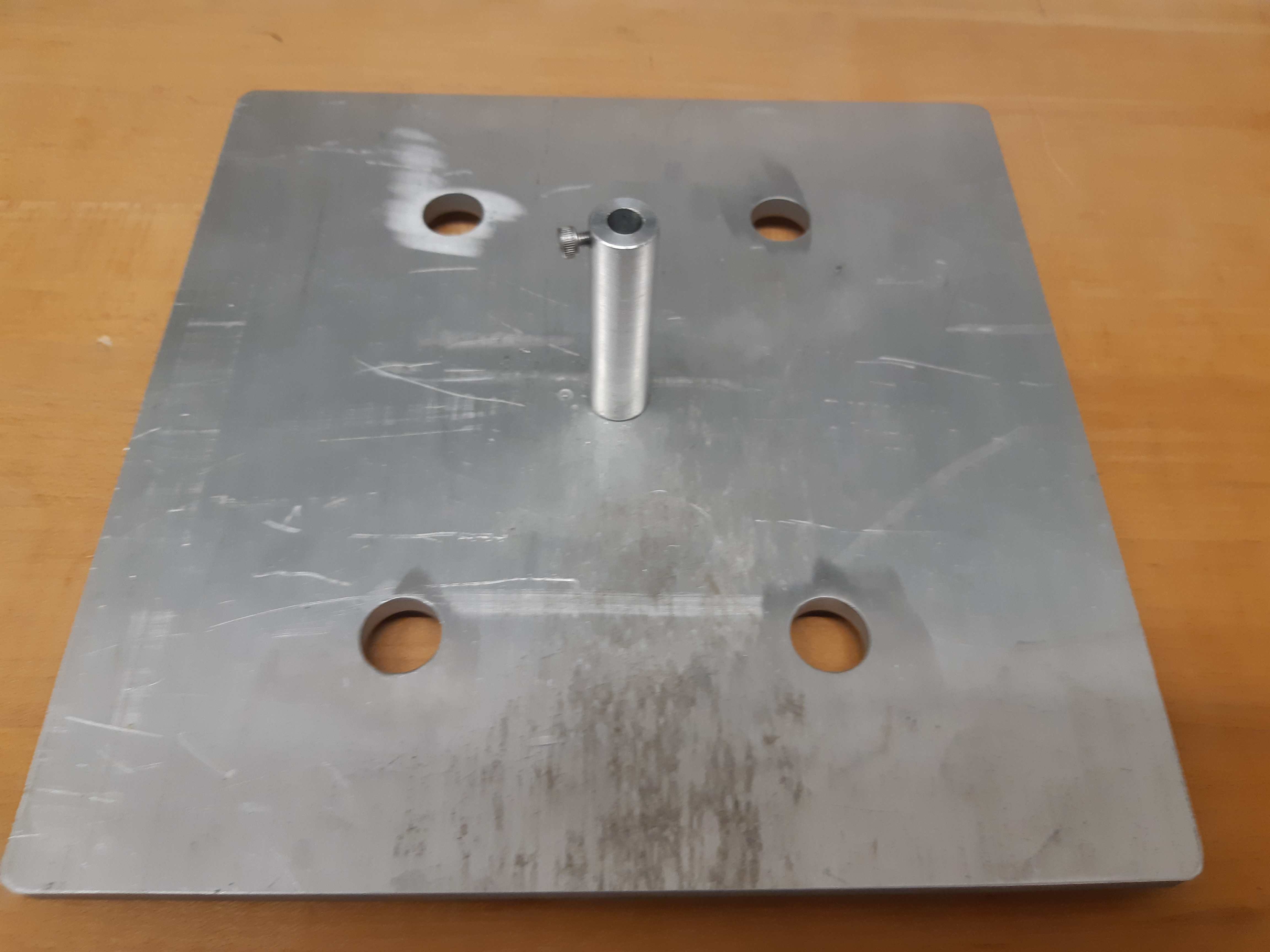
Spacer stuck onto the aluminum baseplate.
Quantity |
Part |
|---|---|
1pc |
Central Pivot Assembly(Incomplete) |
Upwards Assembly: Part 1
Quantity |
Part |
|---|---|
1pc |
Central Pivot Assembly(Incomplete) |
1pc |
“Collar 1” 3D printed piece. |
1pc |
“Collar 2” 3D printed piece. |
1pc |
Aluminum “Lower Base” |
1pc |
Aluminum “Collar Mount” |
1pc |
Flanged Sleeve Bearing for 1/2” Shaft Diameter and 3/4” Housing ID, 1/2” Long |
1pc |
Clamping Two-Piece Shaft Collar for 1/2” Diameter |
1pc |
Notched Disc Spring for 1/2” Shaft Diameter, 0.0330” Thick |
4pc |
Male-Female Threaded Hex Standoff, 1/2” Hex Size, 1-1/2” Long, 1/4”-20 Thread Size |
4pc |
1/4”-20 Thread Size Locknuts |
2pc |
Thrust Ball Bearing for 1-1/2” Shaft Diameter, 2-1/8” OD, 0.437” Thick |
1pc |
Notched Disc Spring for 1/2” Shaft Diameter, 0.0330” Thick |
Slide the first 3D printed collar piece “Collar 1” down the cylindrical spacer on the baseplate, and ensure that it lies flat on the baseplate.
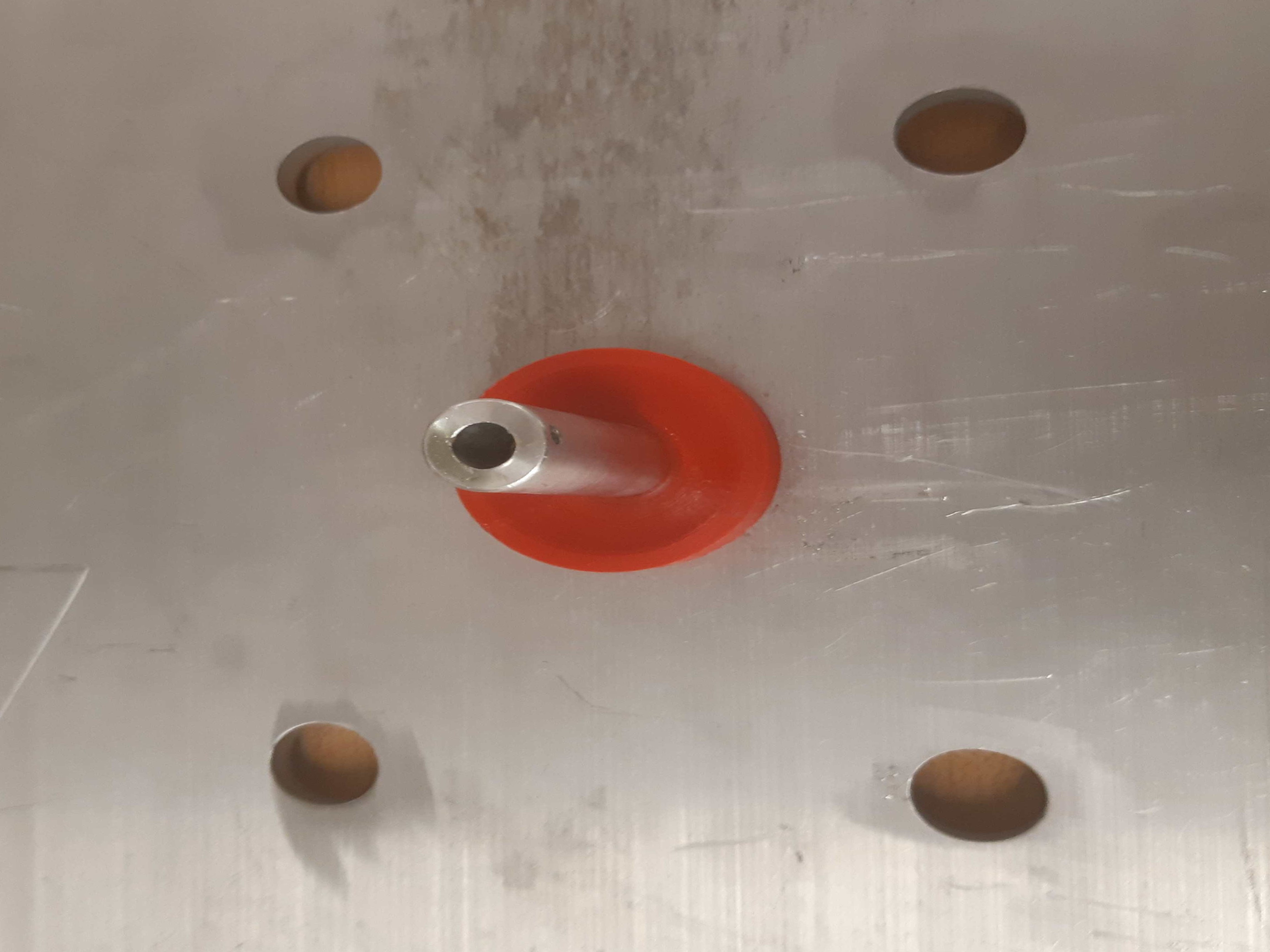
3D printed collar around the aluminum spacer, on the baseplate.
Slide the wide thrust bearing around the 3D printed collar, and ensure that it lies flat on the baseplate.
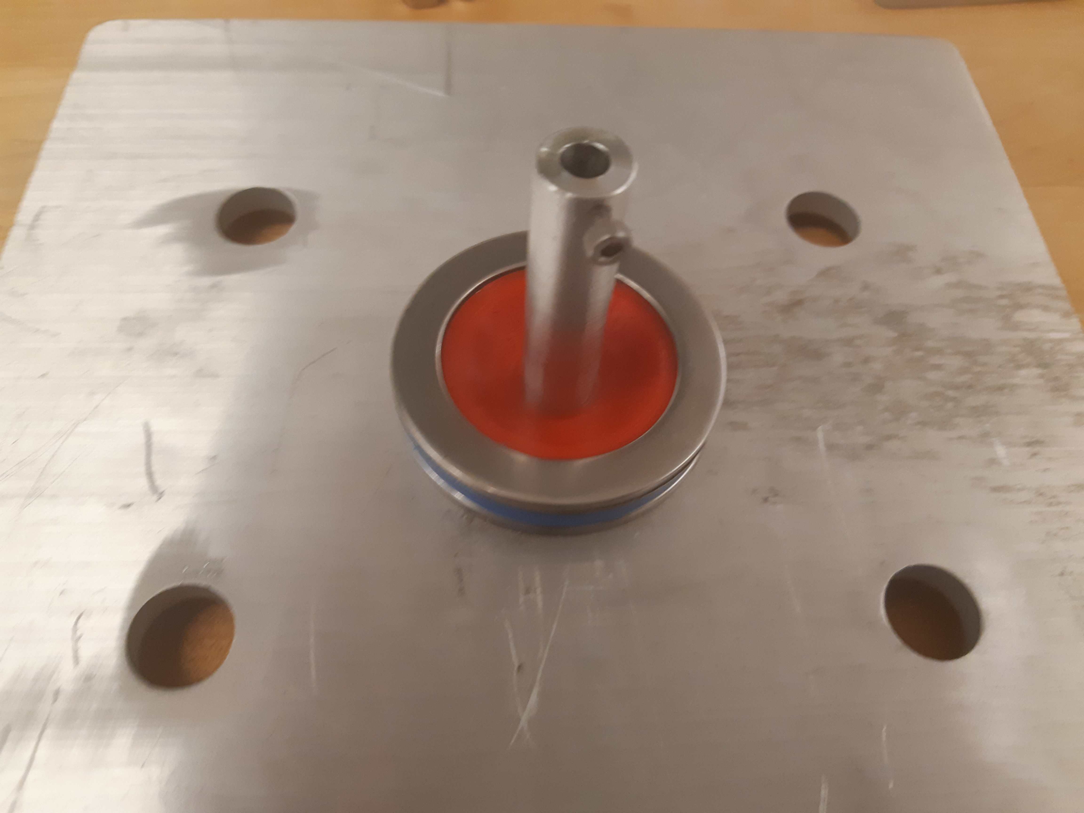
Thrust bearing around the 3D printed collar, on the baseplate.
Slide the “Lower Base” aluminum platform around the cylindrical spacer, and ensure that it lies flat on top of the thrust bearing. Slide the flanged bearing around the cylindrical standoff until the flange lies flat on top of the “Lower Base”.
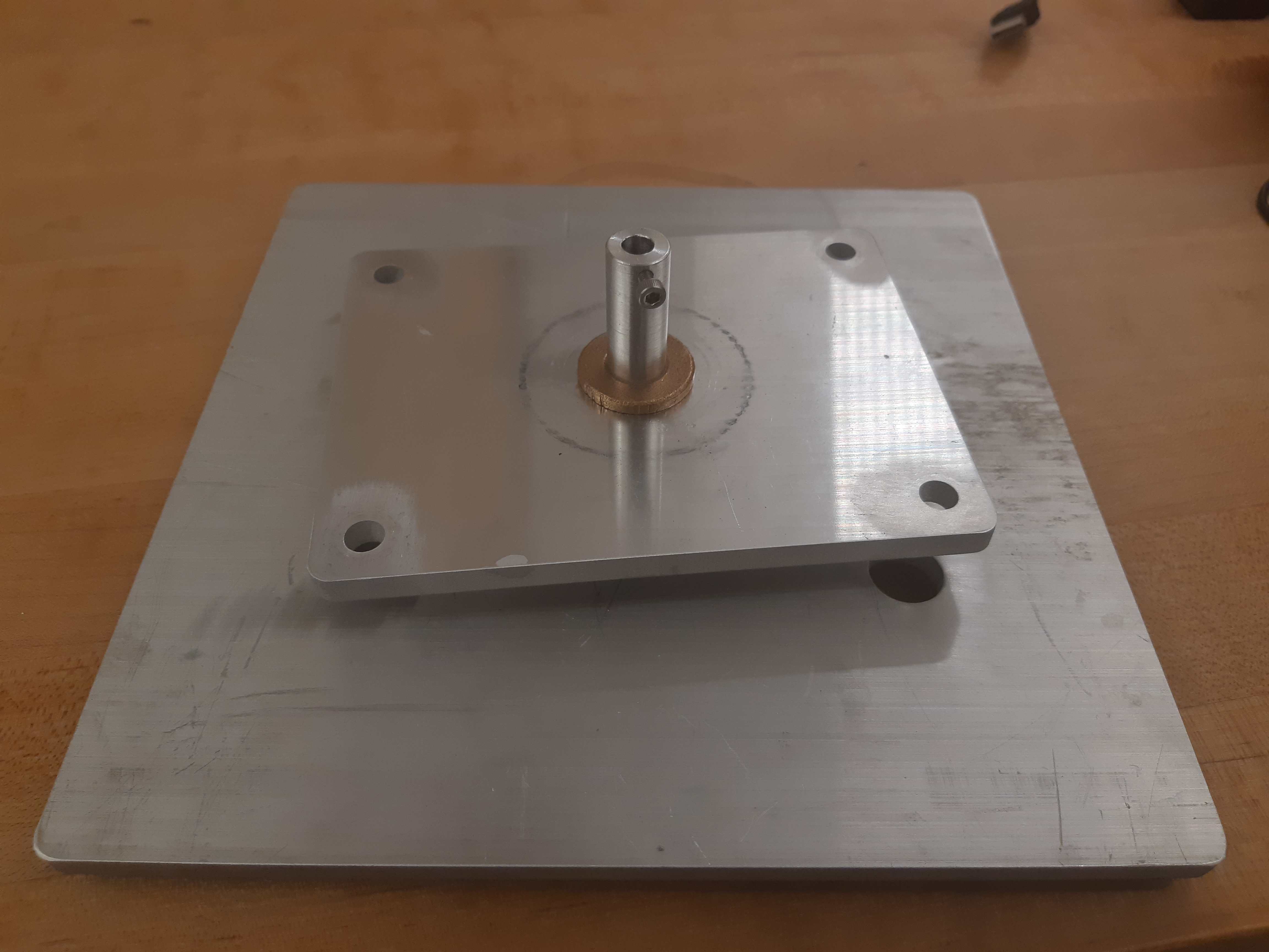
Aluminum “Lower Base” on top of the thrust bearings, with flanged bearing
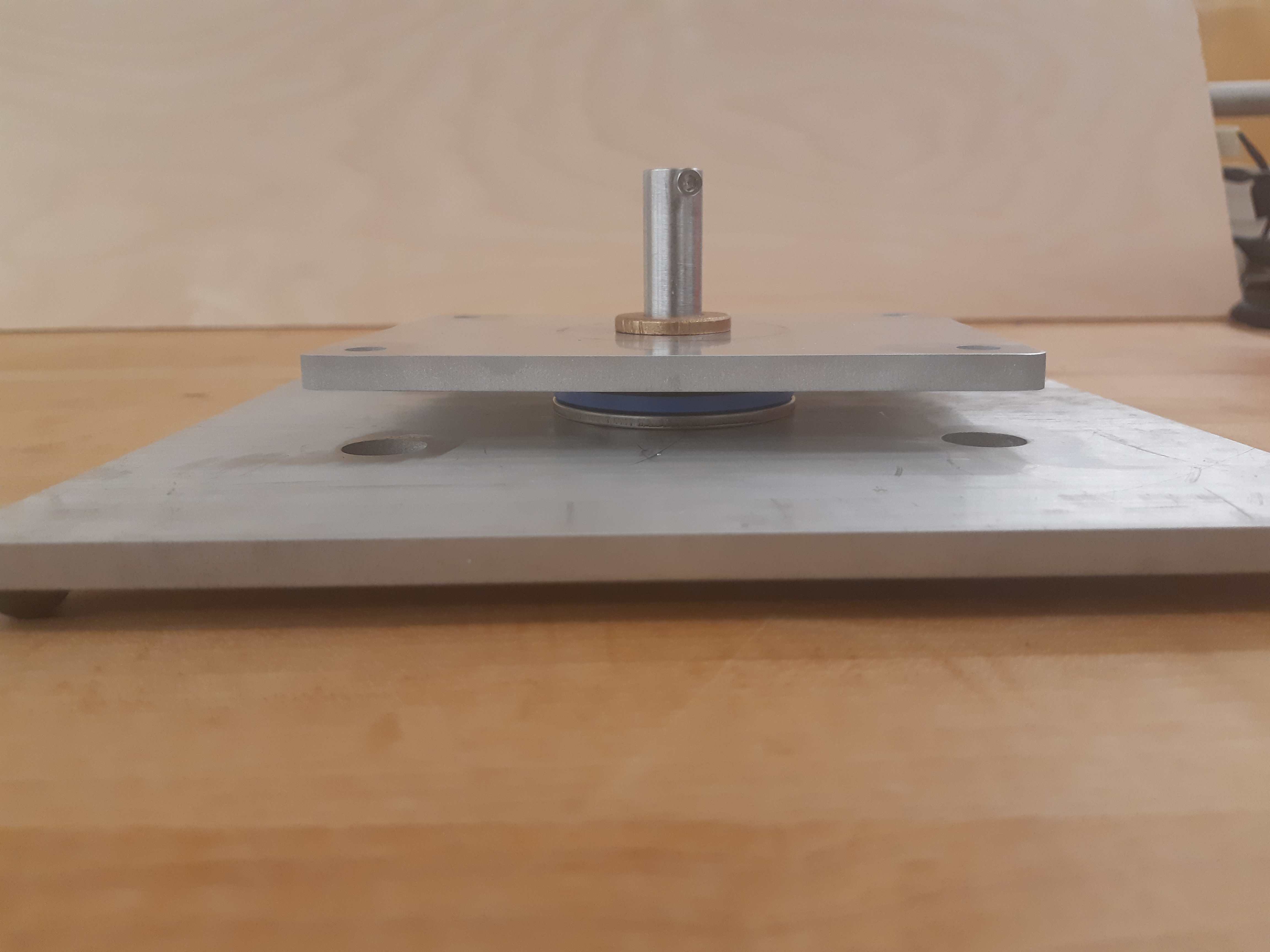
Another view of the “Lower Base”
Slide the second 3D printed collar piece “Collar 2” down the cylindrical spacer, and ensure that it lies flat on the “Lower Base”. Slide the second wide thrust bearing around the 3D printed collar, and ensure that it lies flat on the lowest platform.
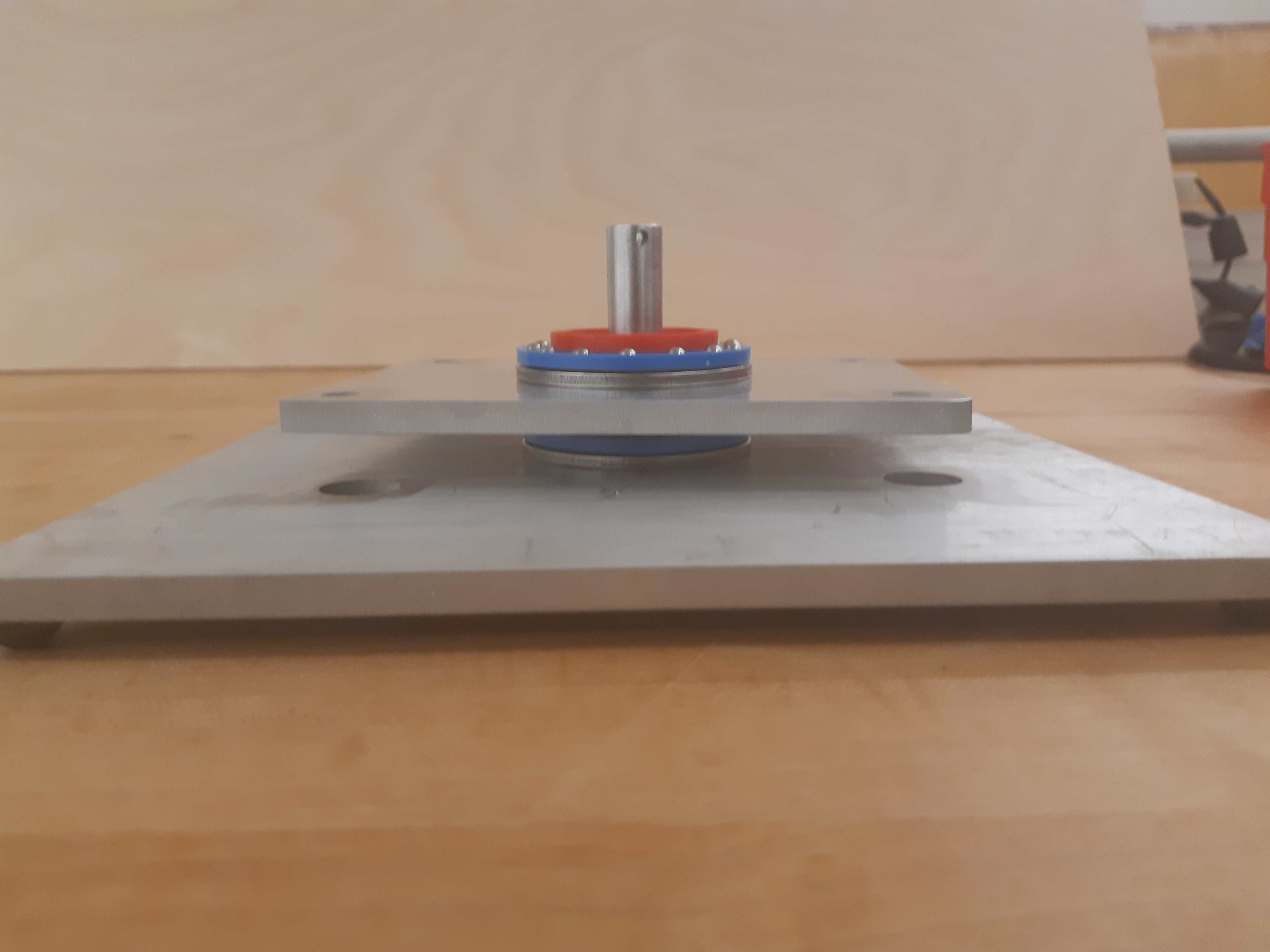
3D printed collar around the aluminum spacer, on top of the “Lower Base”, with thrust bearing around the 3D printed collar.
Slide the circular aluminum piece “Collar Mount” down the cylindrical standoff, and ensure that it lies flat on top of the thrust bearing.
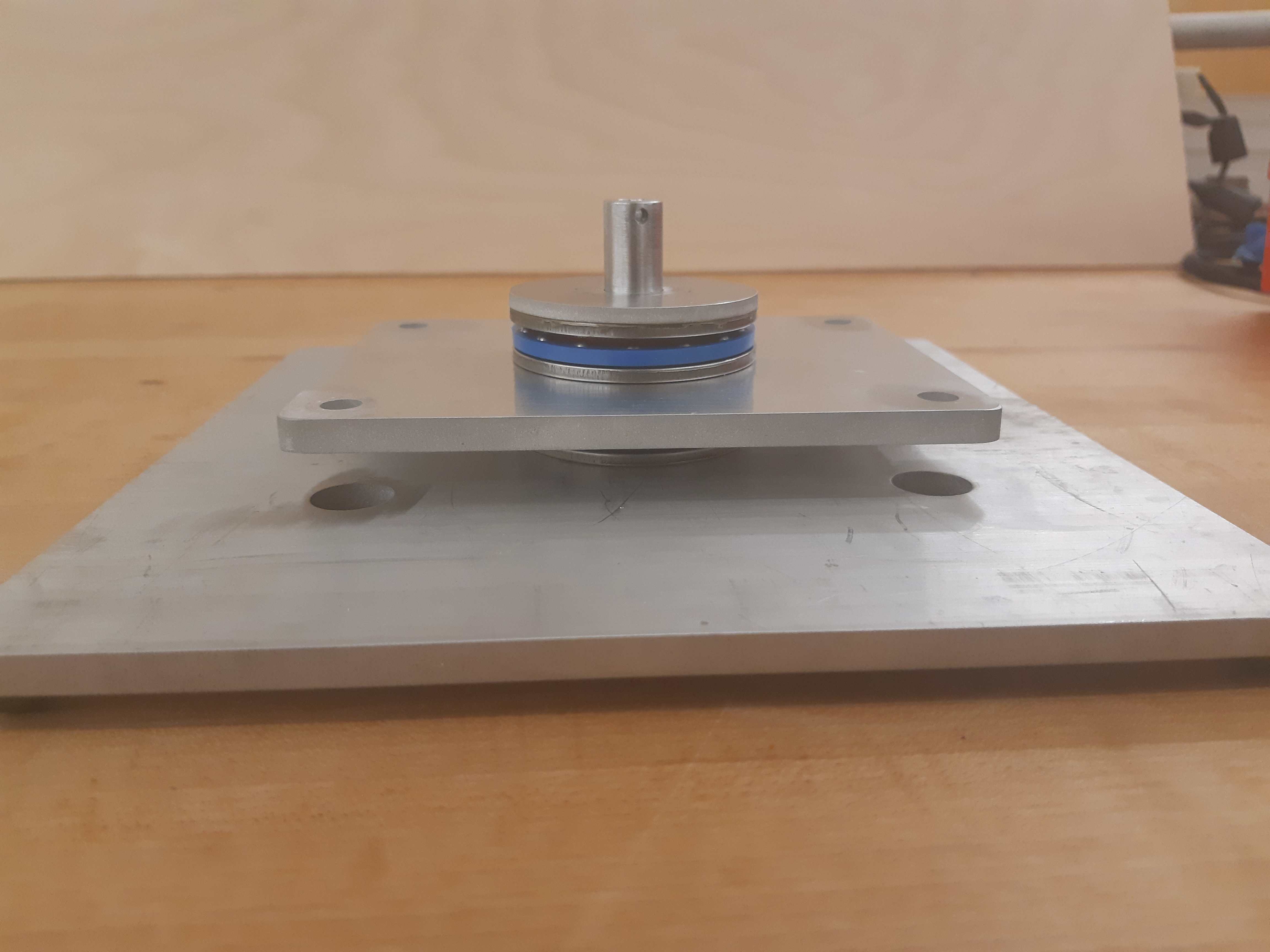
Collar Mount on top of the thrust bearing.
Slide a disc spring and a 1/2” shaft collar down the cylindrical spacer. Applying pressure on top of the shaft collar, secure the shaft collar with the provided screws. This compresses the 2 thrust bearings, allowing the lowest aluminum platform to rotate freely, but remain constrained.
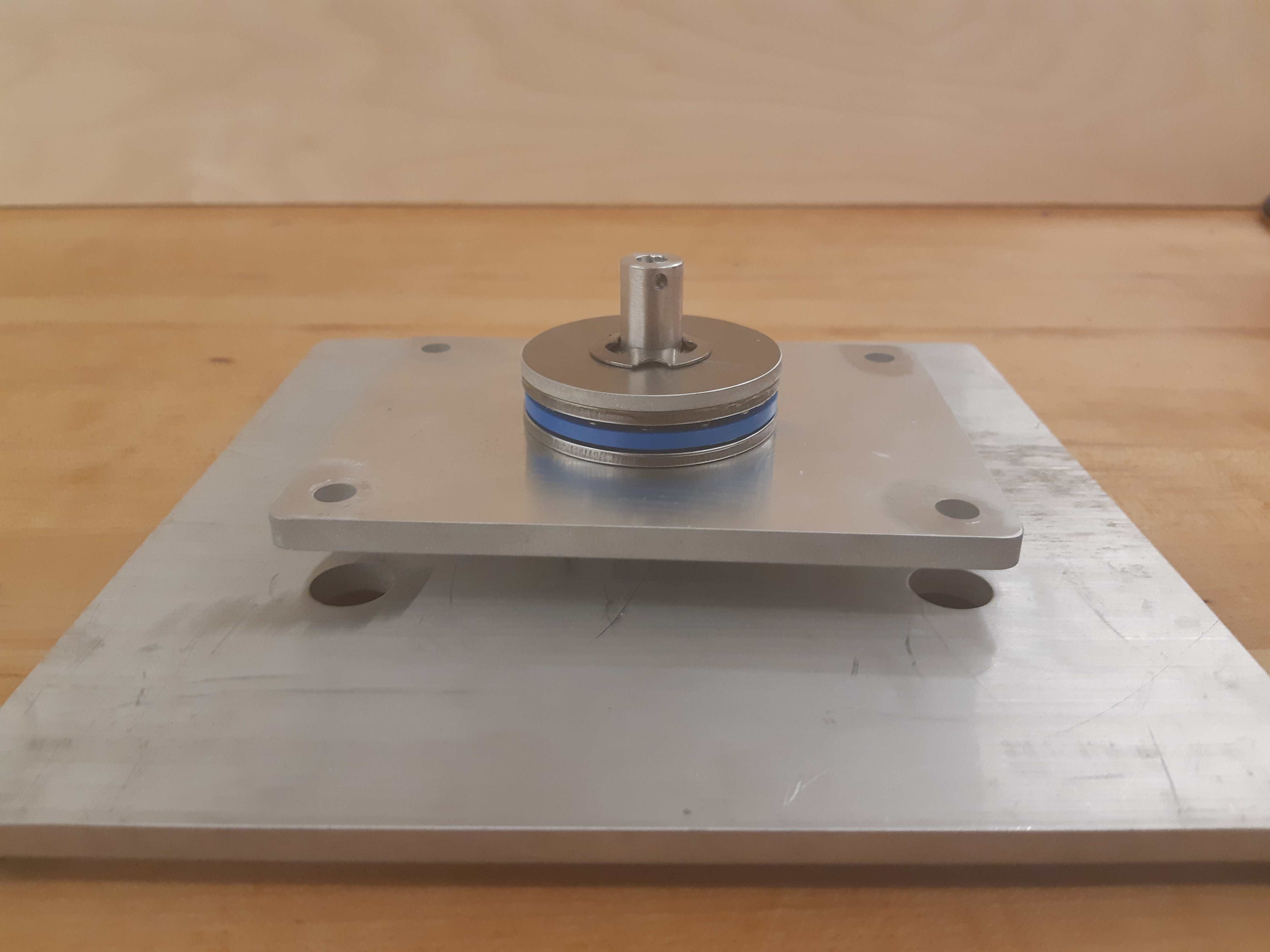
Disc spring around the aluminum spacer, on top of the “Lower Base”
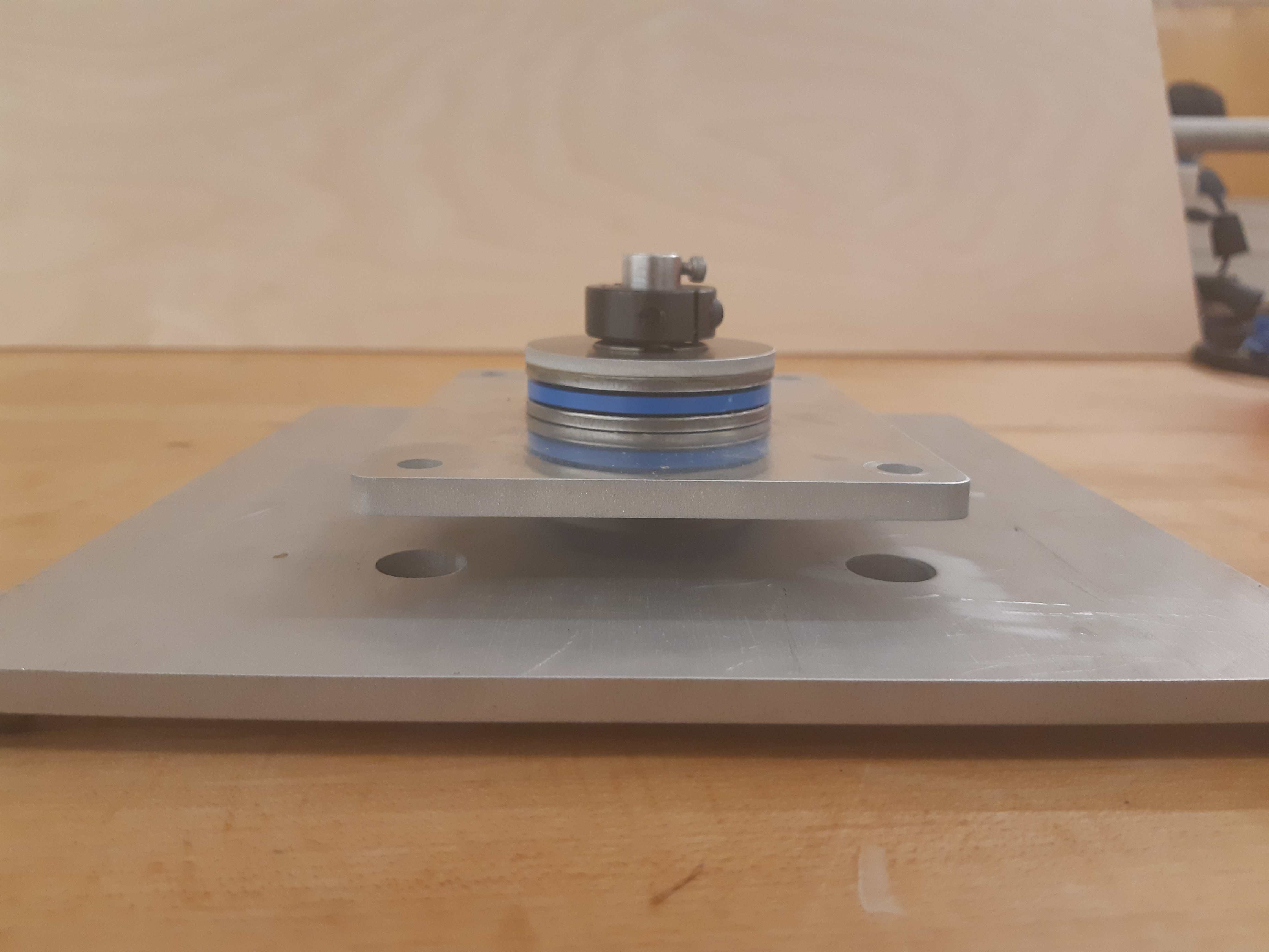
Shaft collar around the aluminum spacer, on top of the disc spring.
Using 4 1/4”-20 screws, secure 4 threaded standoffs with length 1-1/2” onto the 4 holes on the lowest aluminum platform. Secure them at the base with locknuts.
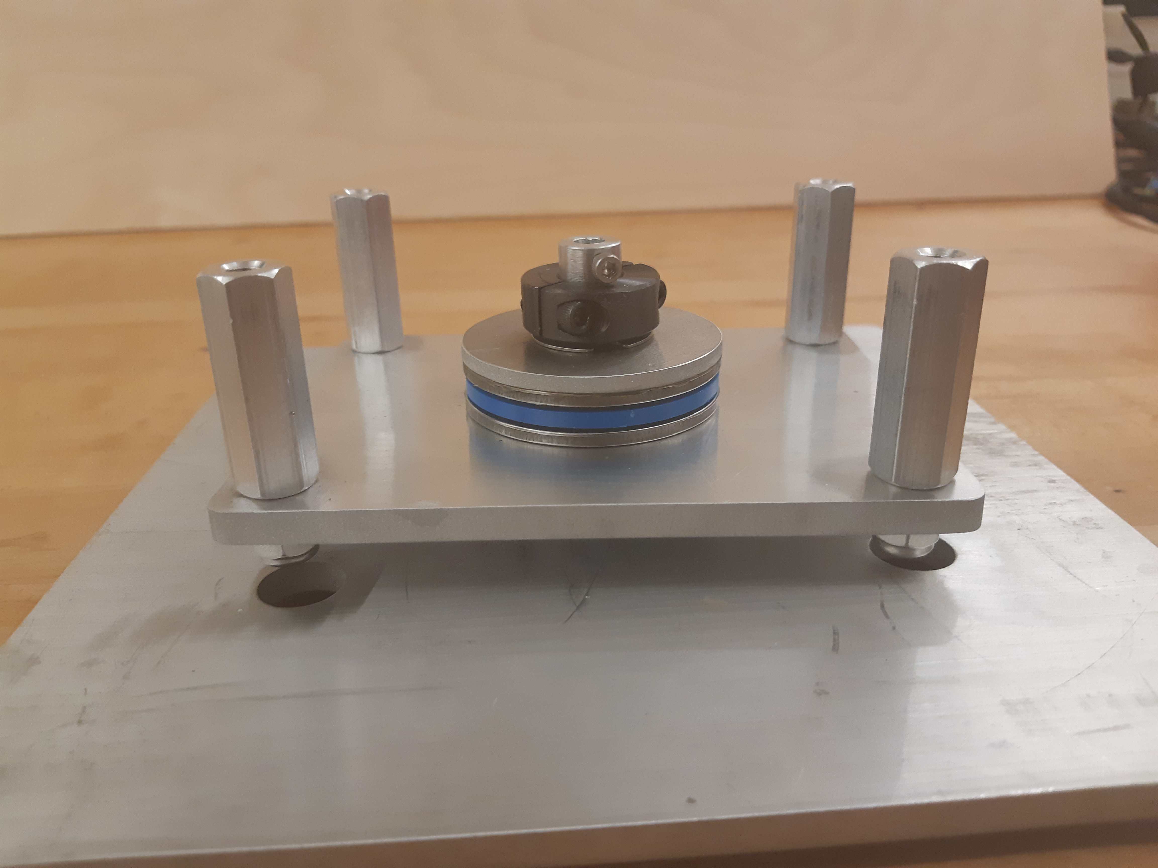
Standoffs on top of the “Lower Base”, secured by locknuts
Quantity |
Part |
|---|---|
1pc |
Central Pivot Assembly(Incomplete) |
Shaft Preparation
Quantity |
Part |
|---|---|
1pc |
Rotary Shaft 316 Stainless Steel, 6mm Diameter, 400 mm Long |
1pc |
Aluminum “Upper Base” |
Slide the 6mm diameter aluminum shaft into the hole of the cylindrical spacer. Slide the second lowest aluminum plate “Upper Base” on top of the 4 threaded standoffs of length 1-1/2”.
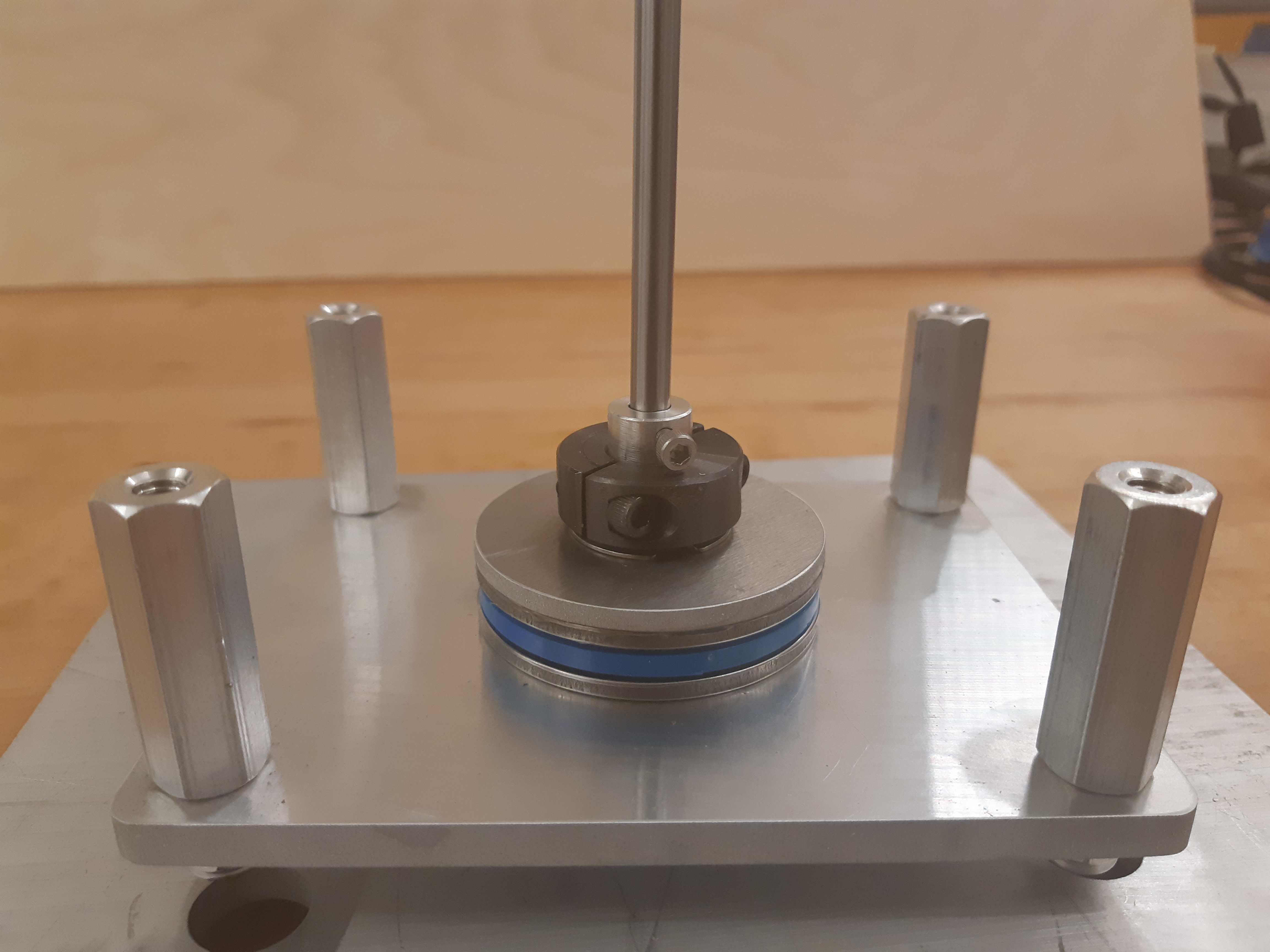
6mm diameter shaft in the cylindrical spacer
With a fine marker, mark the height of the upper surface of the “Upper Base” on the aluminum shaft.
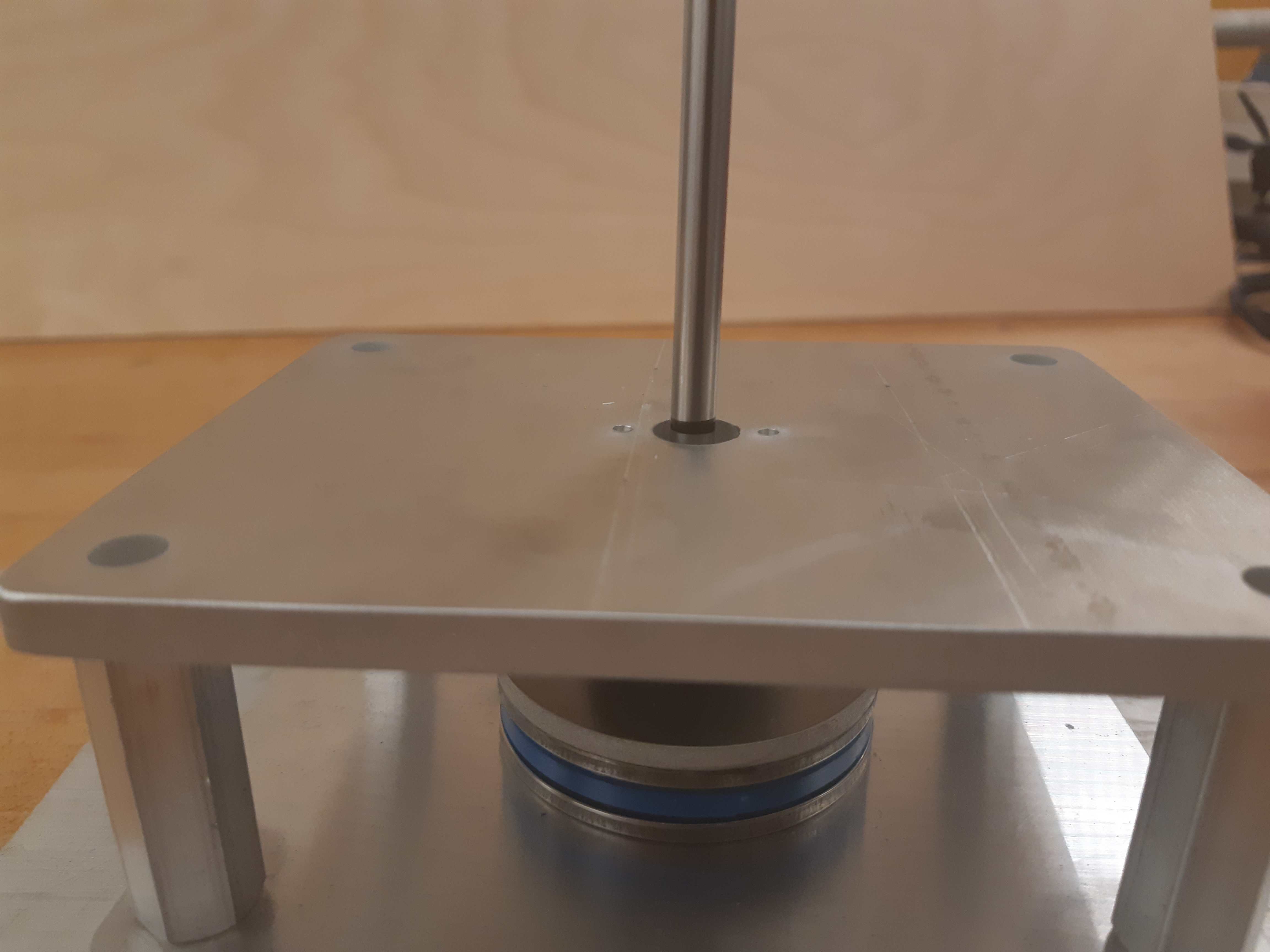
6mm diameter shaft in the cylindrical spacer, with “Upper Base” aluminum piece. Note the marker point on the shaft.
With a fine marker, mark a point 14mm above the upper surface of the second lowest aluminum plate. This is the recommended length of the shaft such that it would fit inside the encoder in the next steps. Using a handsaw, cut the shaft at this length.
Insert the shorter segment of the shaft into the hole of the cylindrical spacer, and ensure that it is a loose fit. Layer the lower portion of the shaft with thin tape to ensure a tight fit. Slide this shaft into the cylindrical standoff and confirm a tight fit. This will be the Horizontal Angle Shaft.

Thin tape is used to pad the 6mm shaft, such that it fits tightly into the hole of the cylindrical spacer
Finally, cut a segment of length 160mm out of the remaining 6mm diameter shaft. This will be the Vertical Angle Shaft.

Shaft cut to 160mm
Quantity |
Part |
|---|---|
1pc |
Horizontal Angle Shaft(the shorter one) |
1pc |
Vertical Angle Shaft(the longer one) |
1pc |
Aluminum “Upper Base” |
Upwards Assembly: Part 2
1pc |
Central Pivot Assembly(Incomplete) |
|---|---|
1pc |
AEDM-5810-Z12 Optical Encoder |
1pc |
Horizontal Angle Shaft |
2pc |
M2.5x12mm bolts |
2pc |
M2.5 locknuts |
4pc |
Male-Female Threaded Hex Standoff, 1/2” Hex Size, 3/4” Long, 1/4”-20 Thread Size |
4pc |
Male-Female Threaded Hex Standoff, 1/2” Hex Size, 3” Long, 1/4”-20 Thread Size |
1pc |
“Upper Base” |
2pc |
Axle Mounts from previous steps |
Slide the encoder base over the “Upper Base” aluminum piece. Secure it with 2 M2.5 bolts and nuts.
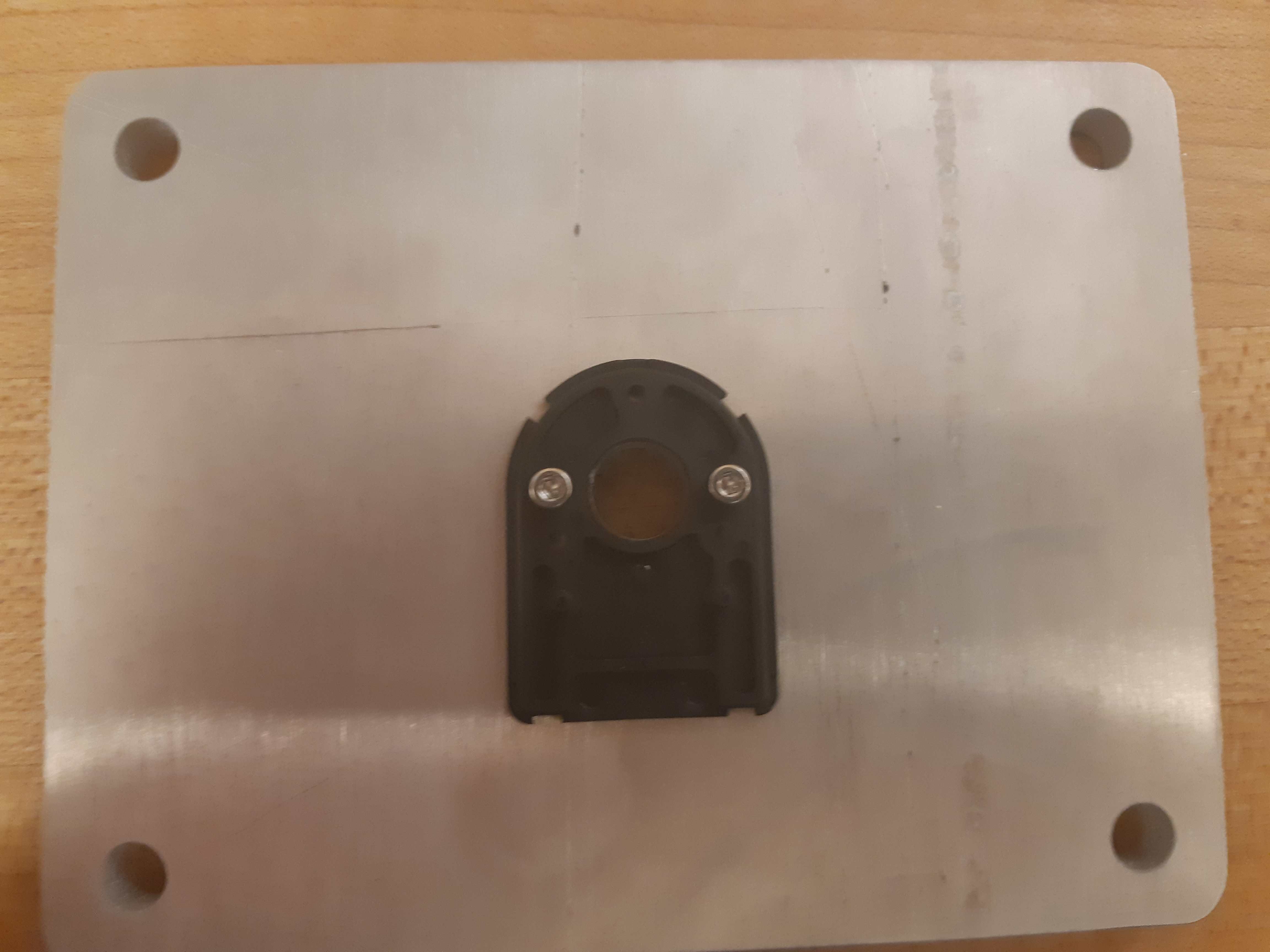
Encoder Base secured on top of the “Upper Base” aluminum plate
Secure the “Upper Base” aluminum piece top of the 4 threaded standoffs, with 4 more threaded standoffs with length 3/4”.
Slide the encoder cover over the 6mm aluminum shaft, and connect it to the encoder base. Following the instructions in the encoder manual, tighten the set-screw connecting the encoder code wheel with the 6mm shaft, using the provided set-screw.
After that, prime the encoder as per the instructions in the Encoder Datasheet so that it is ready for use.
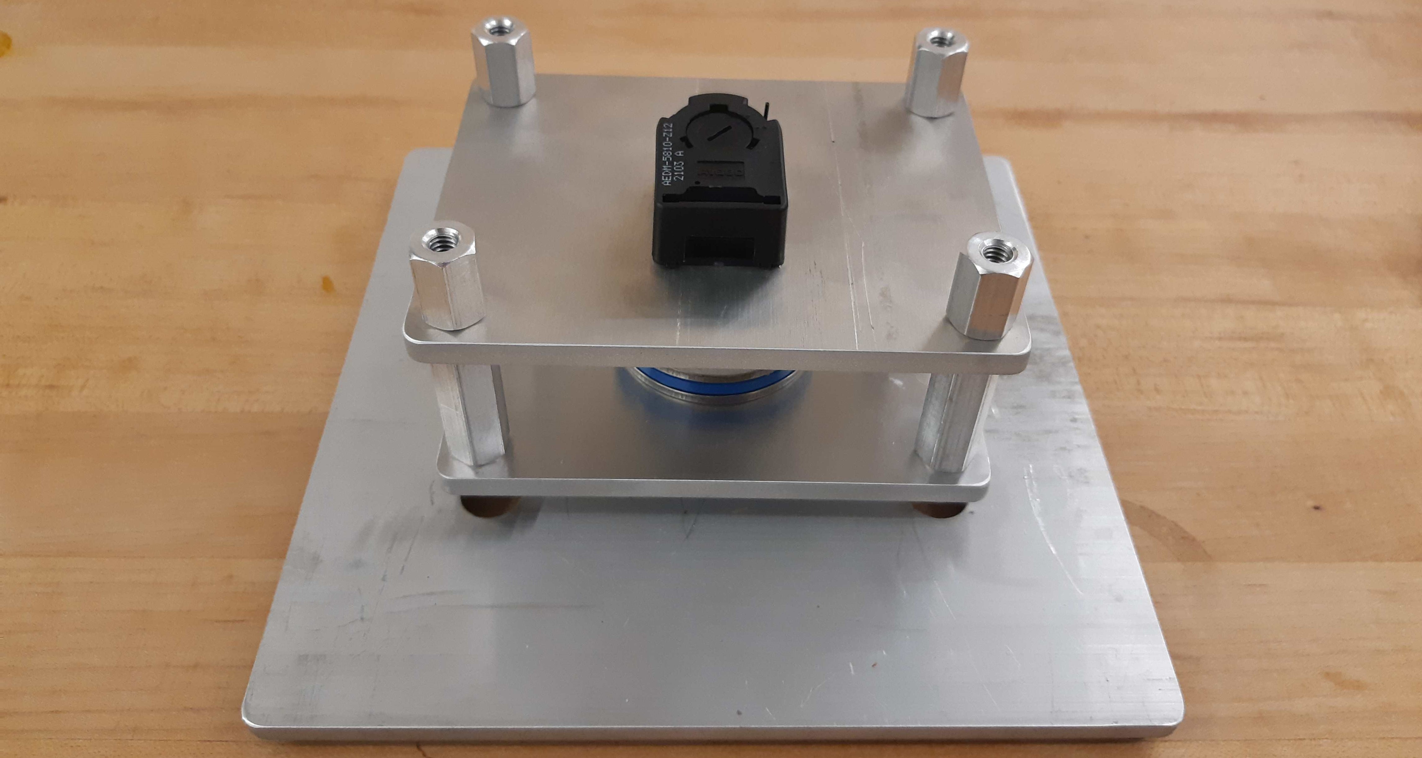
Encoder setup complete, with “Upper Base” secured by aluminum standoffs
On top of the topmost threaded standoffs, place the 2 Axle Mounts. Secure these in place using 4 threaded standoffs of length 3”.
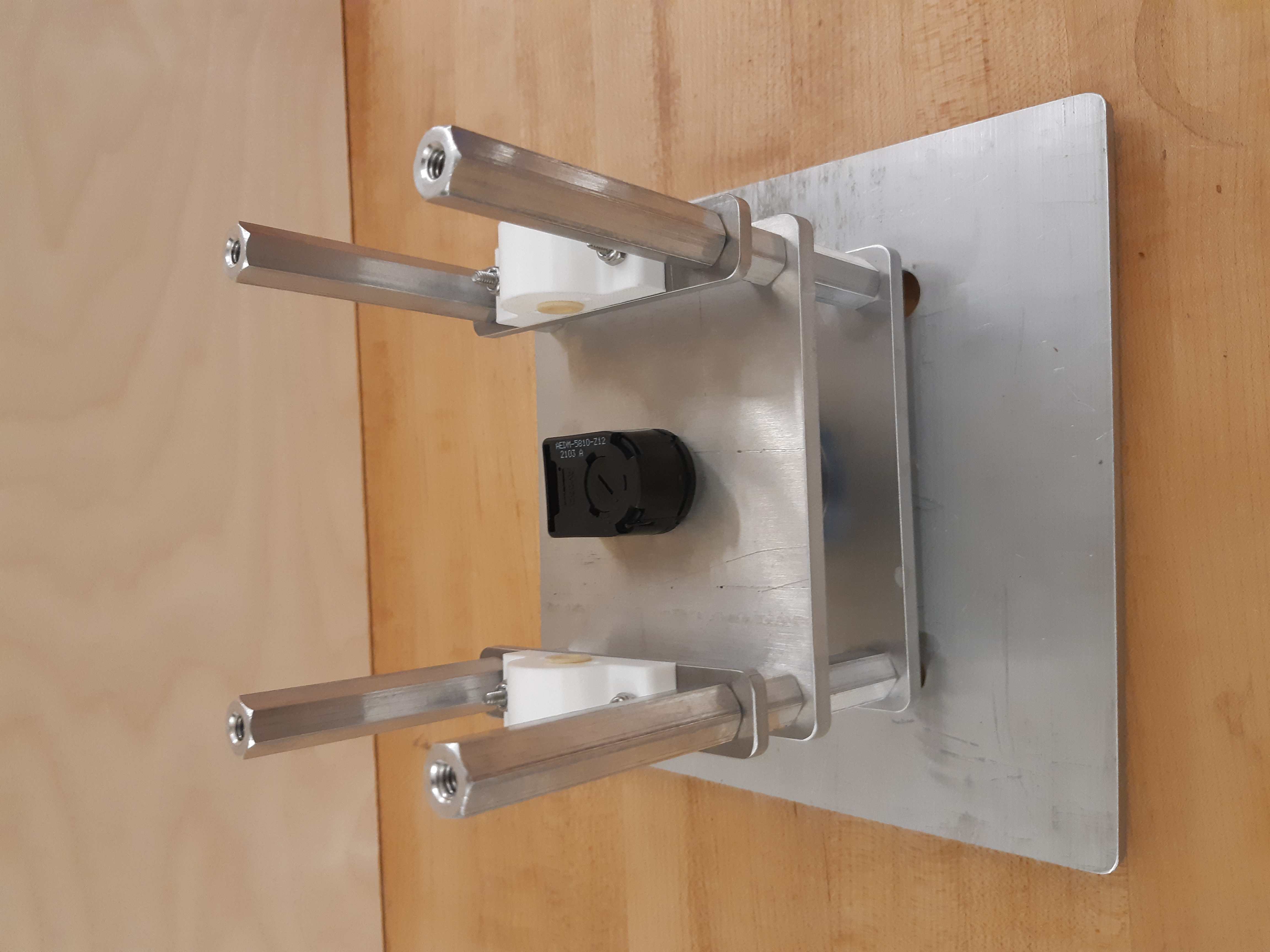
Axle Mounts secured with aluminum standoffs
Quantity |
Part |
|---|---|
1pc |
Central Pivot Assembly(Incomplete) |
Horizontal Shaft Alignment
Parts needed for this step:
Quantity |
Part |
|---|---|
1pc |
Central Pivot Assembly(Incomplete) |
1pc |
Vertical Angle Shaft |
1pc |
AEDM-5810-Z12 Optical Encoder |
4pc |
Screw Collar for 6 mm Shaft diameter |
1pc |
Lower Dowel Mount 3D printed piece |
2pc |
M2.5x12mm screws |
Secure an encoder base onto an Axle Mount using M2.5 screws.
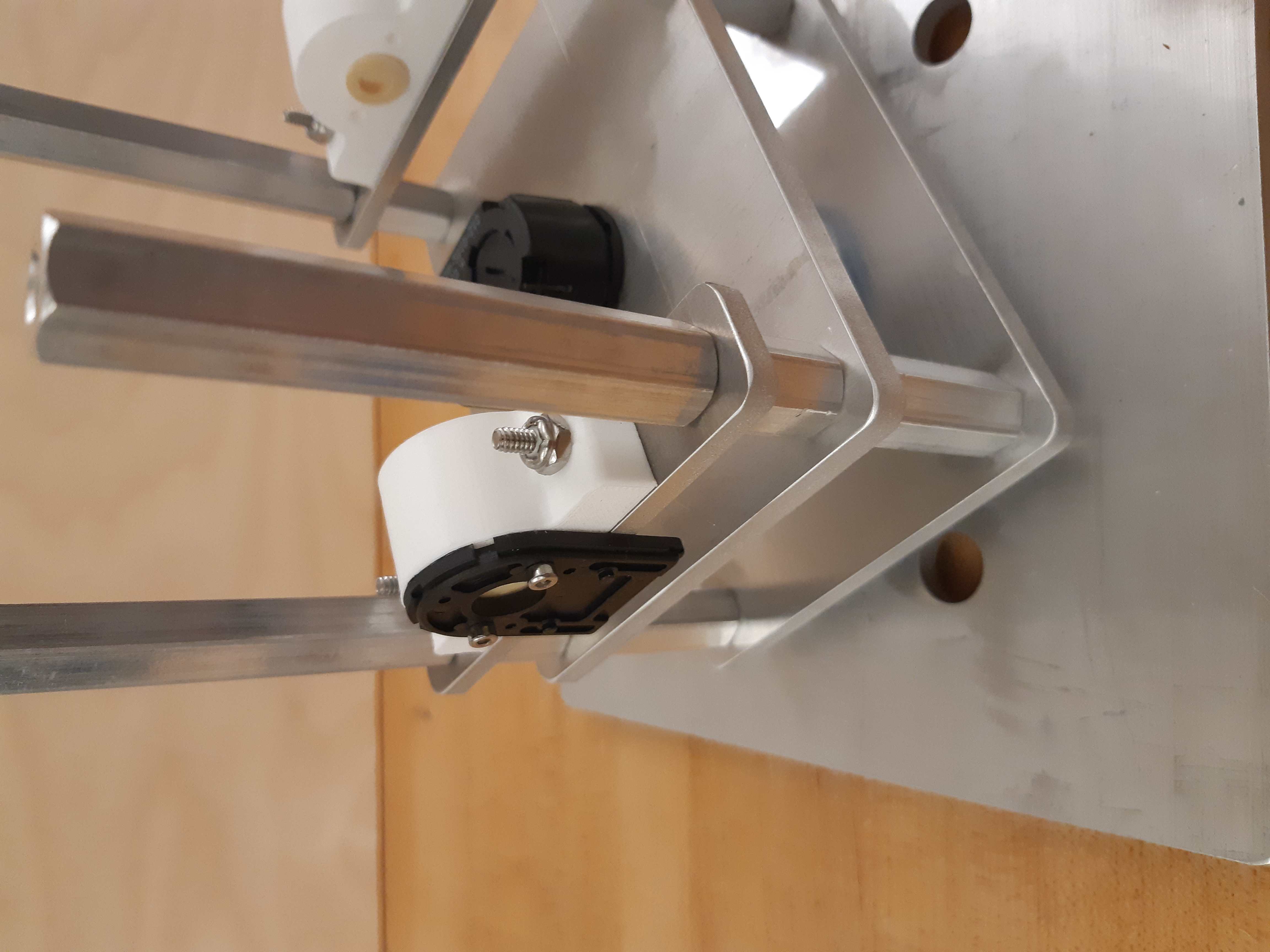
Encoder base secured onto Axle Mount
Arrange the following components in the following order from left-to-right, leaving 14mm of shaft on one end of a shaft-holder. The shaft collars constrain the location of the Lower Dowel Mount on the Horizontal Angle Shaft, ensuring that it remains centered. - Axle Mount - 6mm screw collar - 6mm screw collar - Lower Dowel Mount 3D printed piece - 6mm screw collar - 6mm screw collar - Axle Mount
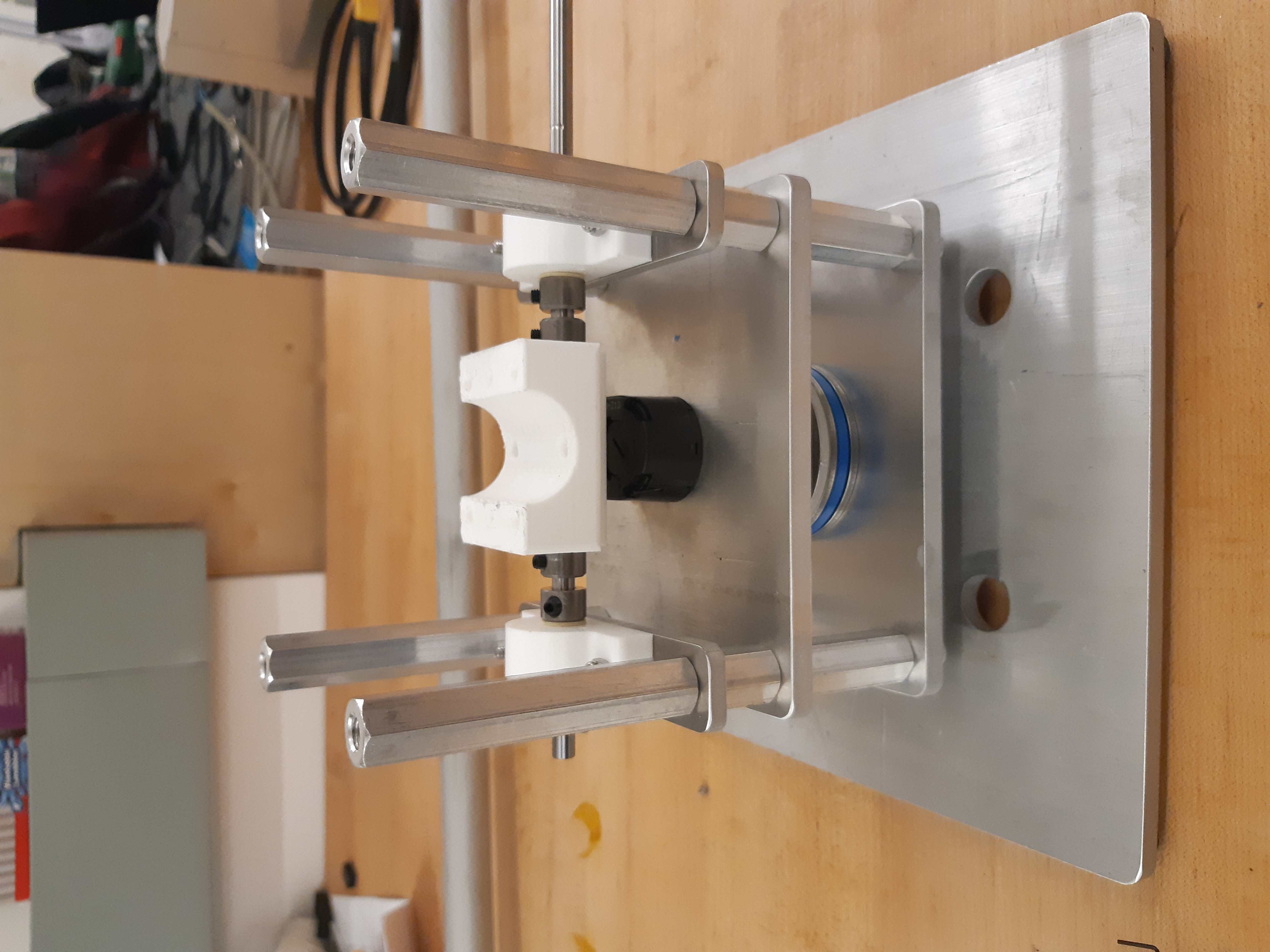
Components aligned properly on the Horizontal Angle Shaft.
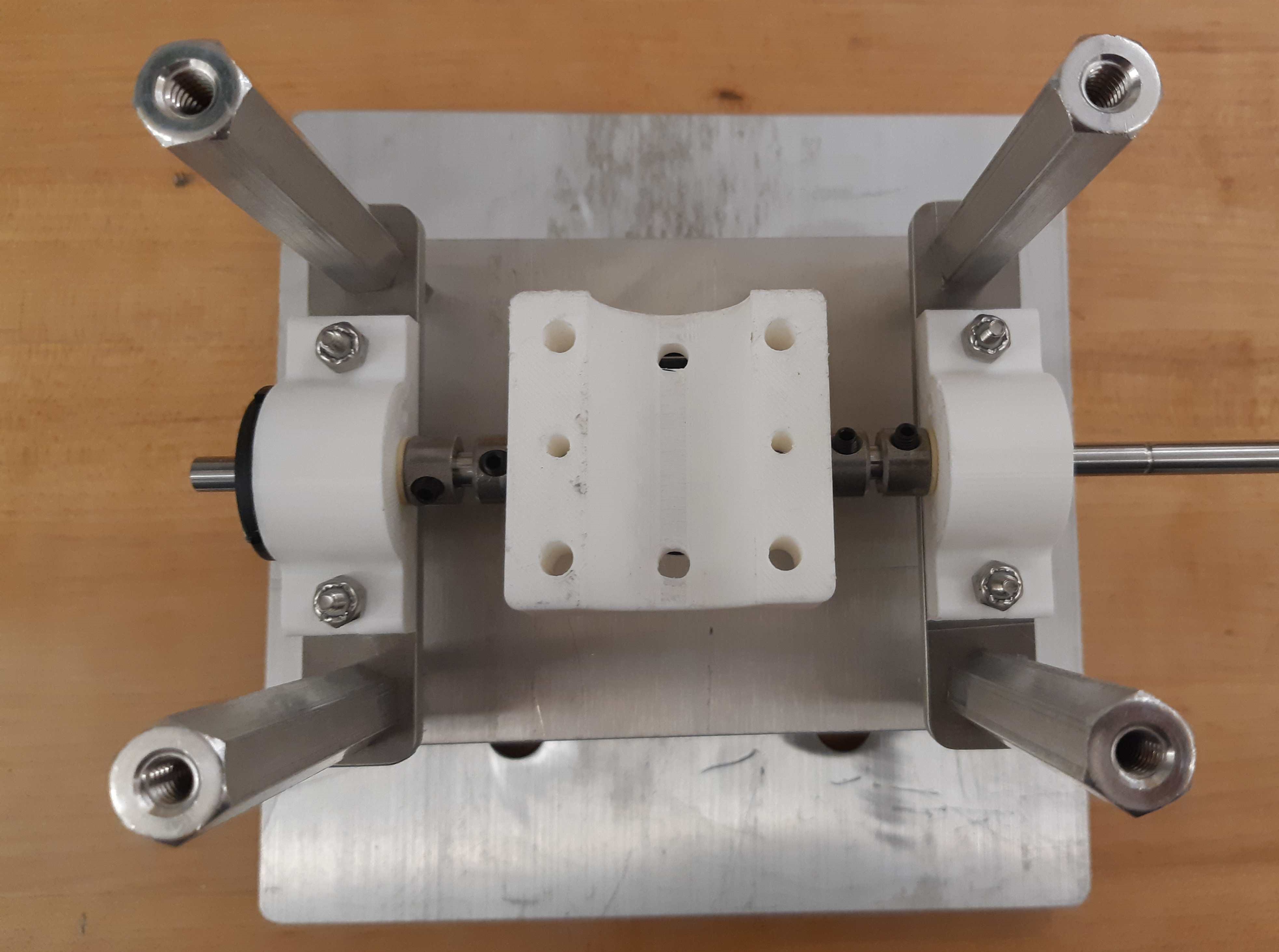
Another view of the components aligned properly on the Horizontal Angle Shaft.
Once the shaft collars have been positioned, epoxy the Lower Dowel Mount onto the shaft. This prevents the Lower Dowel Mount from slipping on the shaft.
After aligning the shaft such that there is 14mm of shaft on one end of a Axle Mount, screw in the shaft-collars. This locks the axial position of the shaft, while still allowing rotary motion.
Slide the encoder cover over the Horizontal Angle Shaft, connecting it to the encoder base attached to the Horizontal Angle Shaft
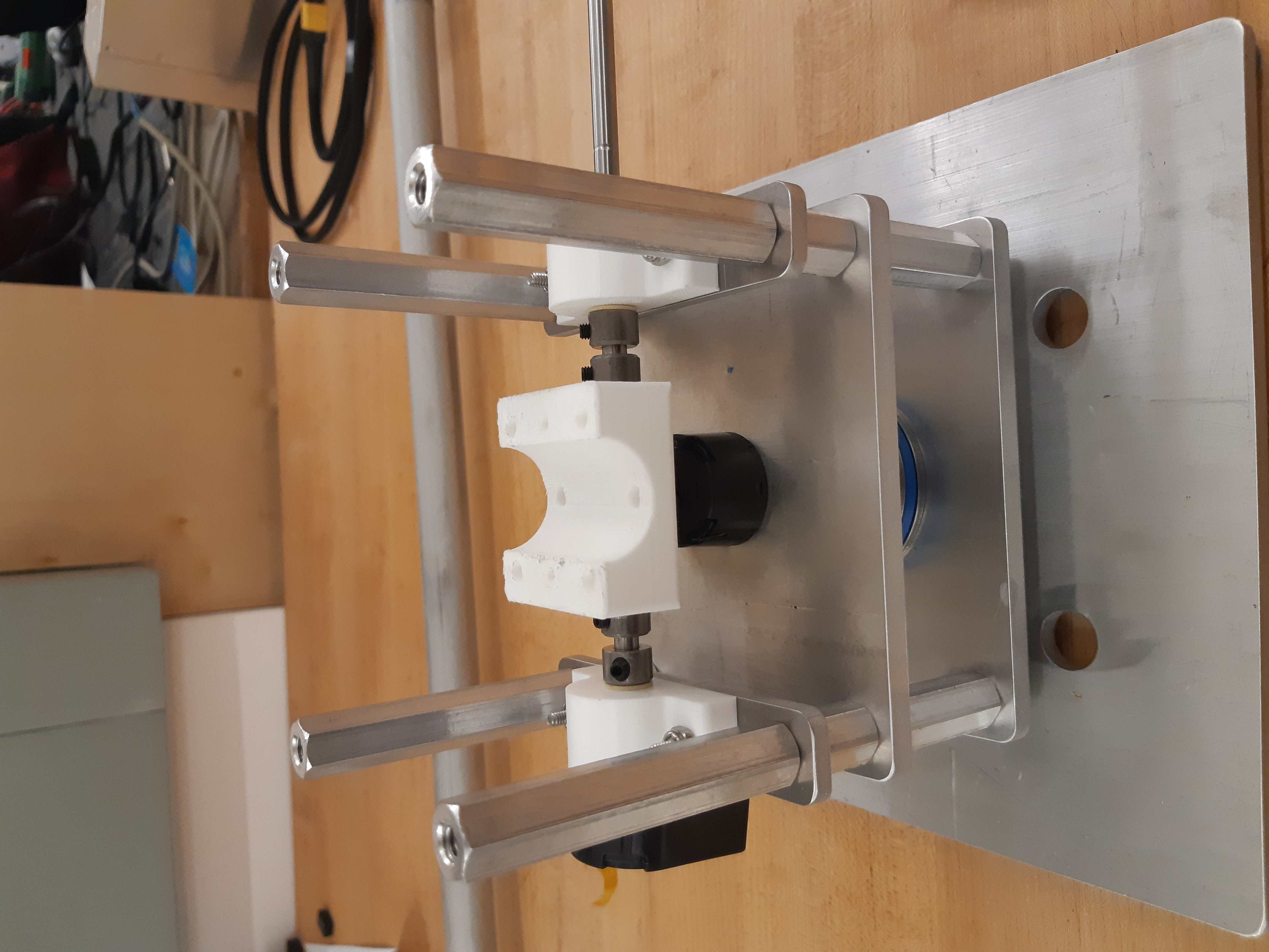
Both encoder installed on the Central Pivot.
Following the instructions in the encoder manual, tighten the set-screw connecting the encoder code wheel with the 6mm shaft, using the provided set-screw. After that, prime the encoder as per the instructions in the Encoder Datasheet so that it is ready for use.
Quantity |
Part |
|---|---|
1pc |
Central Pivot Assembly(Incomplete) |
Upwards Assembly: Part 3
Quantity |
Part |
|---|---|
1pc |
Unfinished Central Pivot Assembly |
1pc |
2m length, 1” OD aluminum tube |
1pc |
Aluminum “Roof Piece” |
1pc |
Aluminum “Electronics Holder” |
1pc |
3D printed “Upper Dowel Mount” |
4pc |
Button Head Hex Drive Screw, 1/4”-20 Thread Size, 1/2” Long |
4pc |
Female Threaded Hex Standoff, 1/4” Hex, 2” Long, 6-32 Thread |
8pc |
Button Head Hex Drive Screw, 6-32 Thread Size, 1/2” Long |
4pc |
Head Screw 10-32 Thread Size, 2” Long, Partially Threaded |
4pc |
Nylon-Insert Locknut 10-32 Thread Size |
Measure a point on the long aluminum boom about 10-20cm from one end, and apply a layer of duct tape around it. This adds friction to the aluminum boom, preventing it from rotating.
Connect the Lower Dowel Mount and the Upper Dowel Mount around the long aluminum tube at the location of the duct tape, securing both ends with 4 10-32 bolts and locknuts.
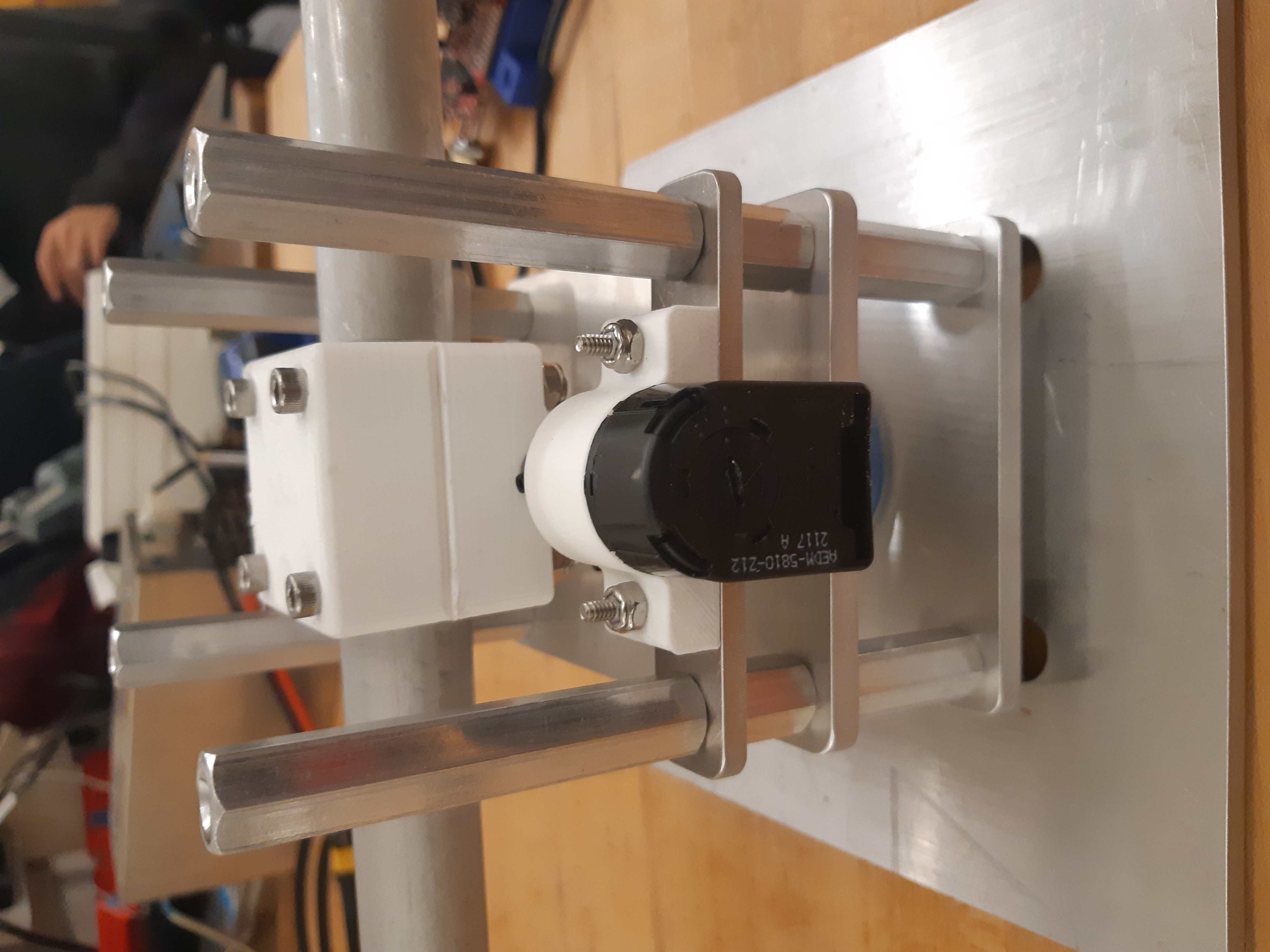
Aluminum tube held by Lower Dowel Mount and Upper Dowel Mount.
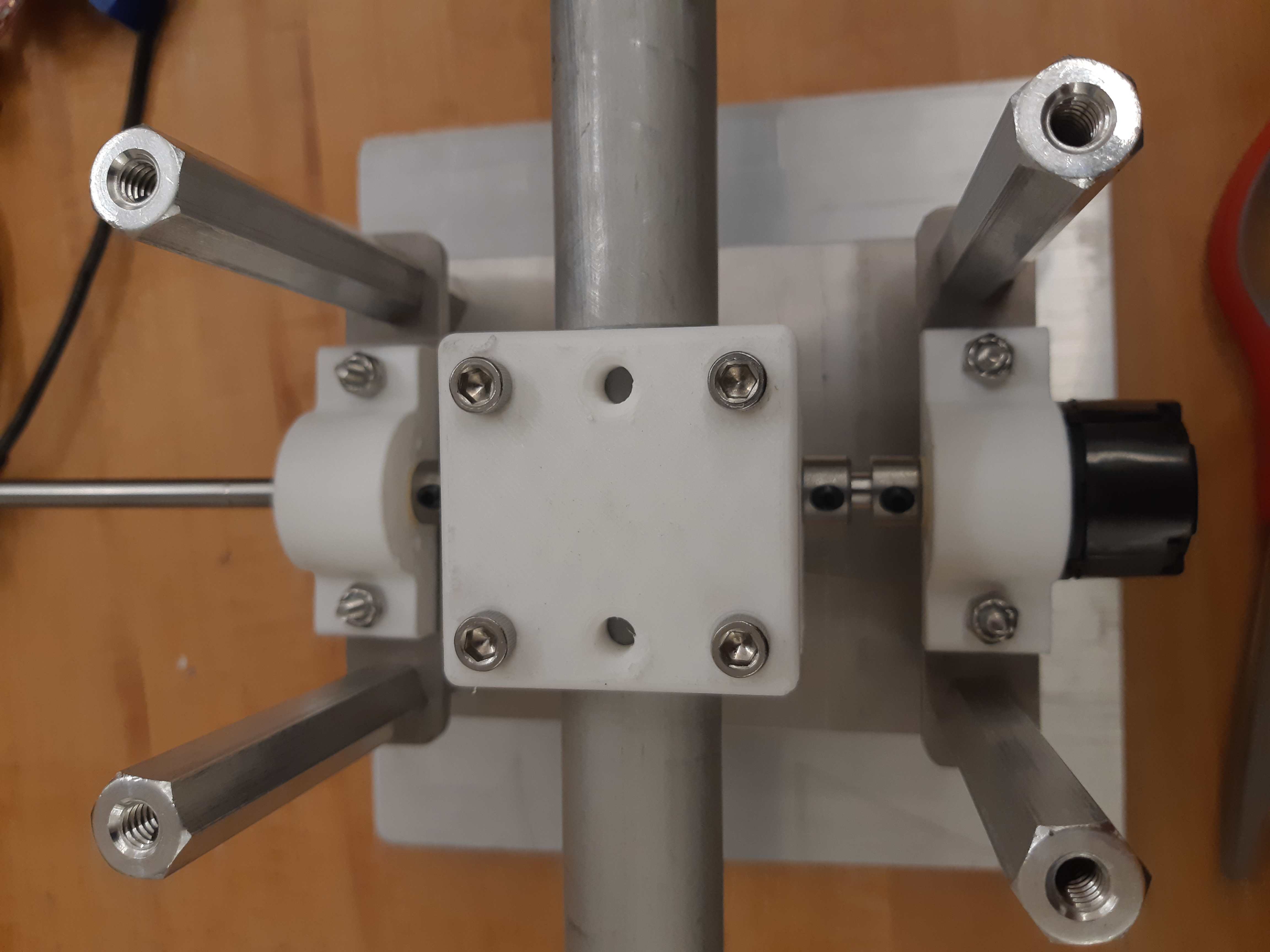
Top view of the aluminum tube held by the Lower Dowel Mount and Upper Dowel Mount.
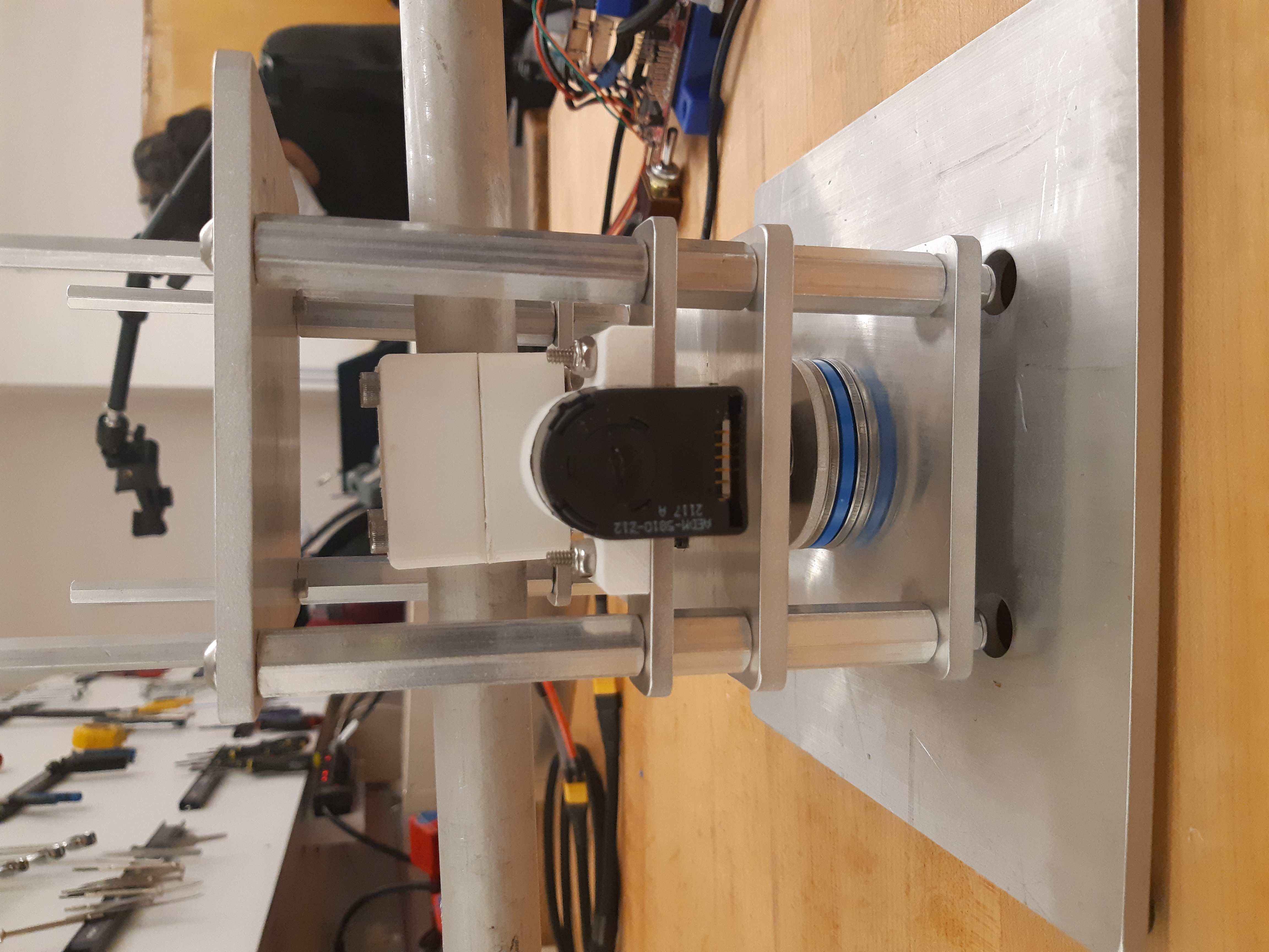
Secure the “Roof” aluminum plate on top of the 4 shaft-collars using 1/4”-20 screws.
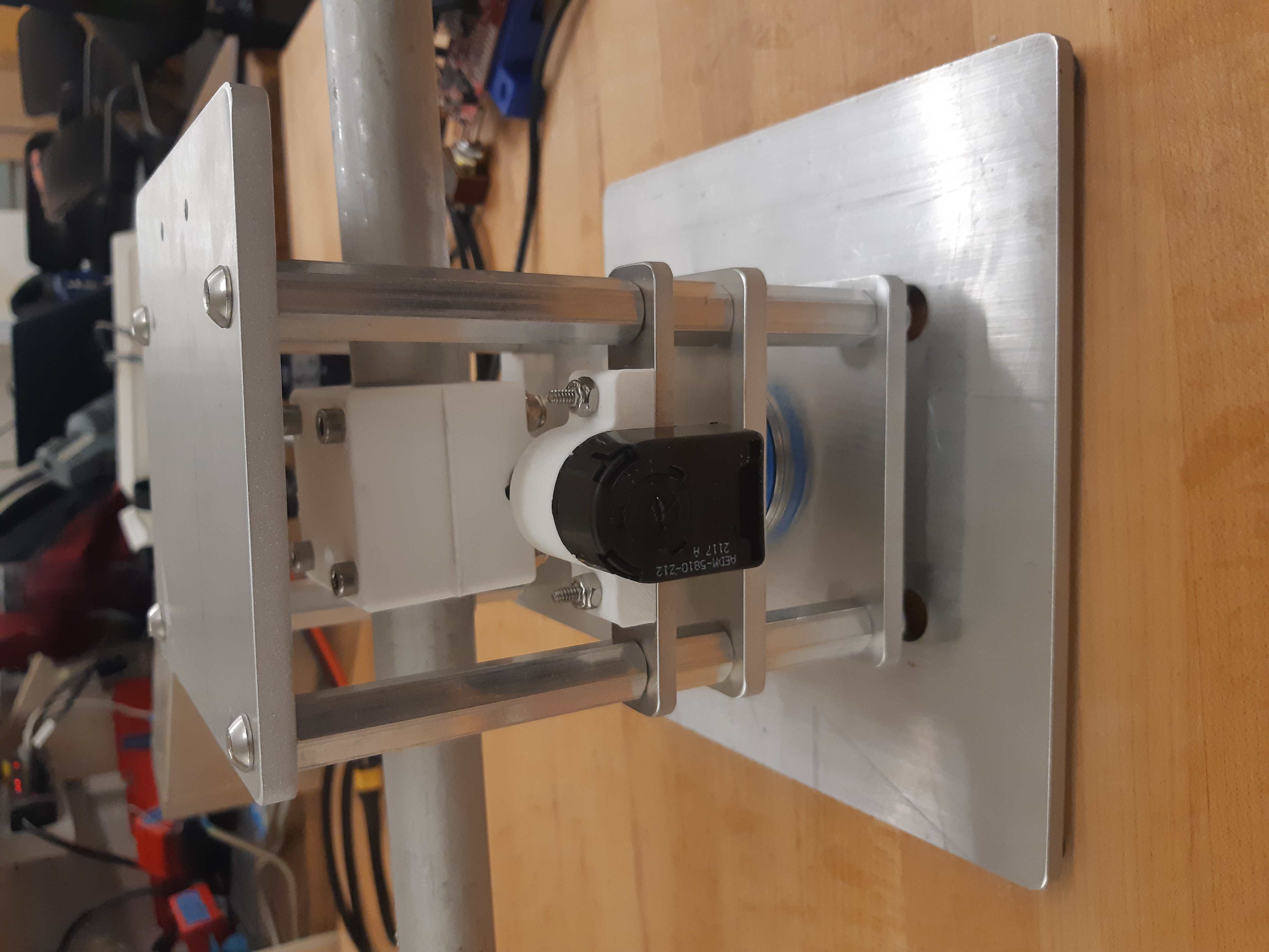
Central Pivot with “Roof” plate installed.
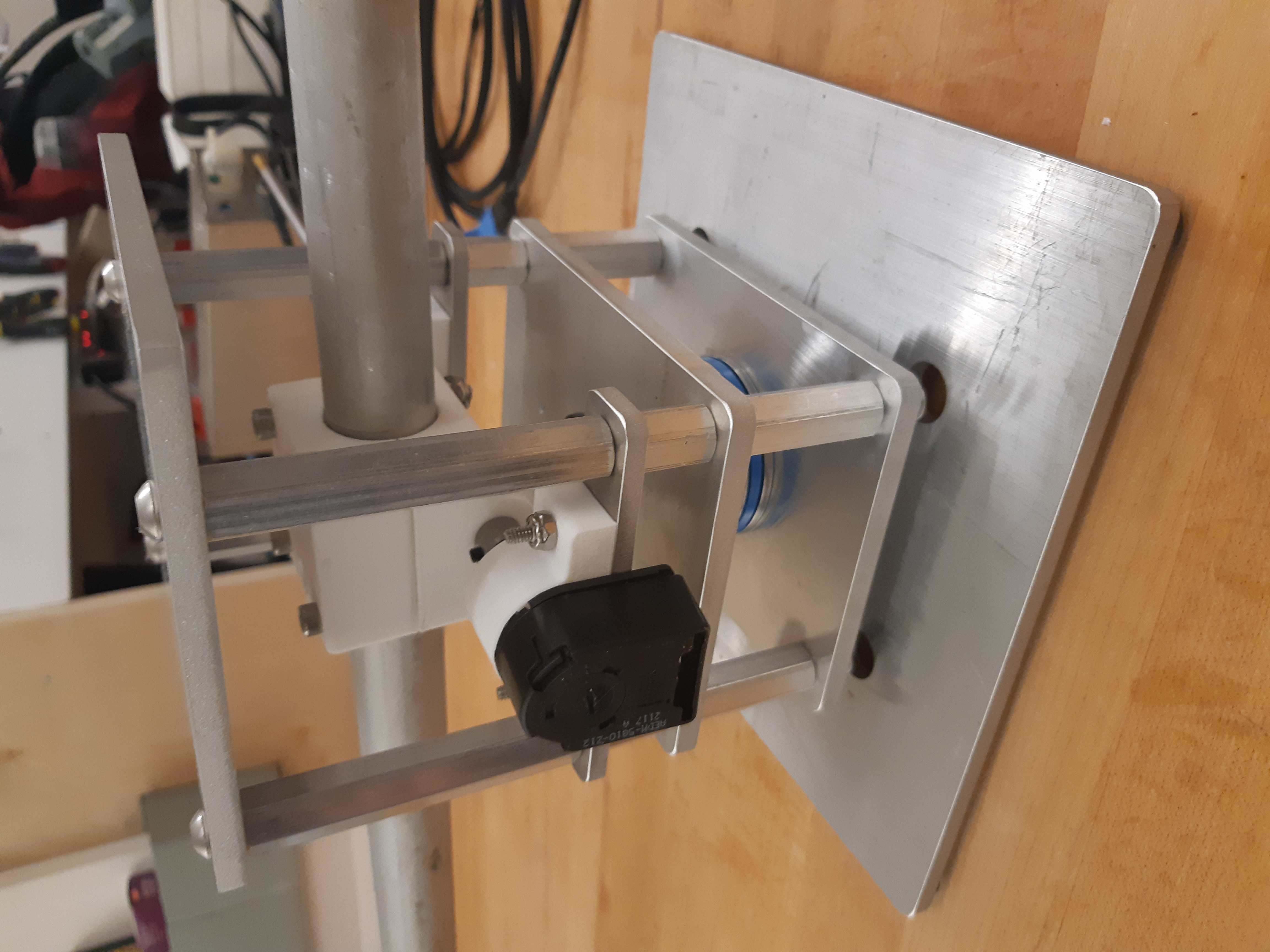
Side view of Central Pivot with “Roof” plate installed.
Secure 4 female threaded hex standoffs with 6-32 threads on top of the upper aluminum plate using 6-32 screws.
6-32 standoffs installed on Central Pivot
Secure the “Electronics Holder” aluminum plate on top of the 4 6-32 standoffs using 6-32 screws.
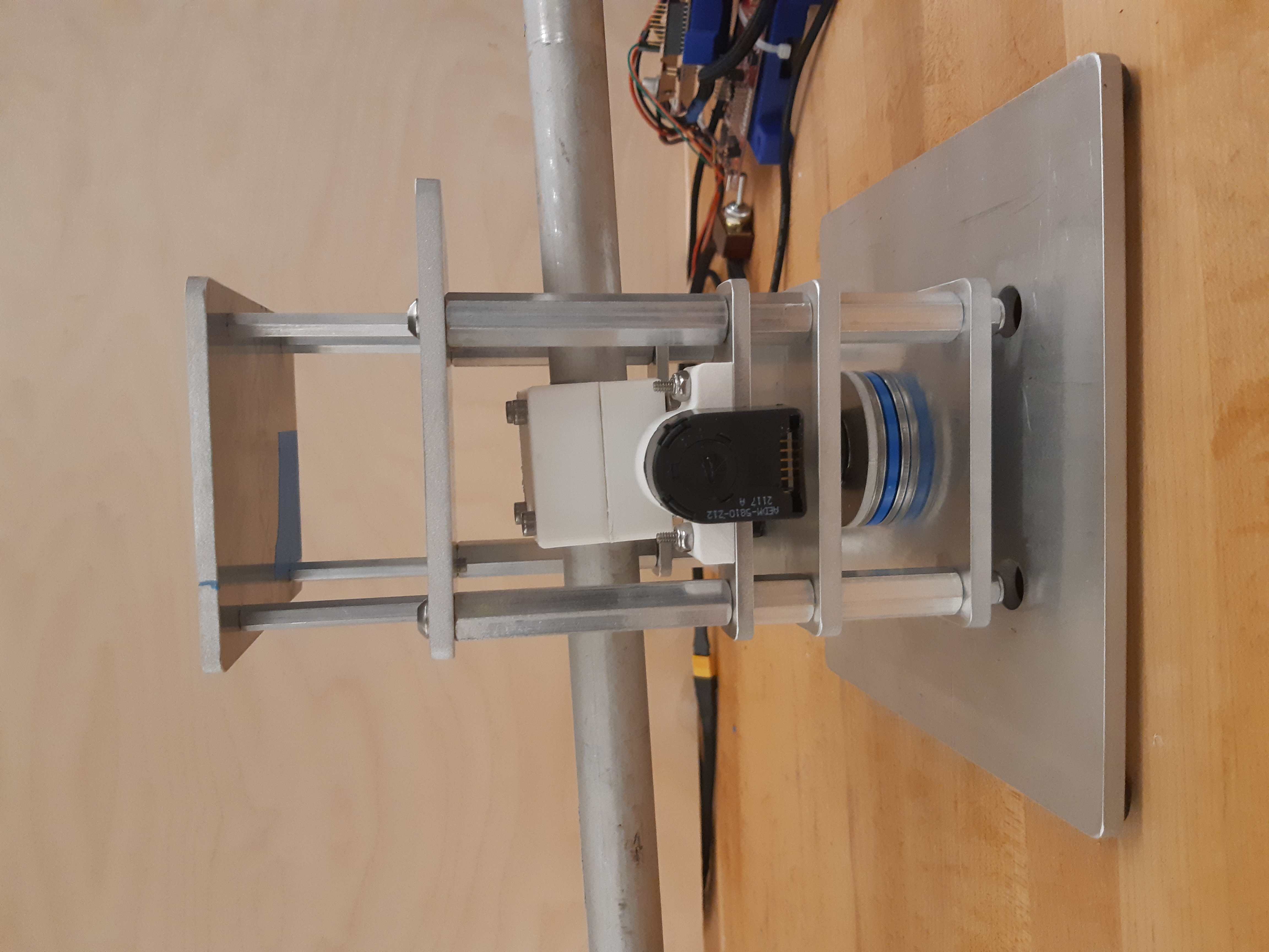
Central Pivot Assembly finished, without wiring
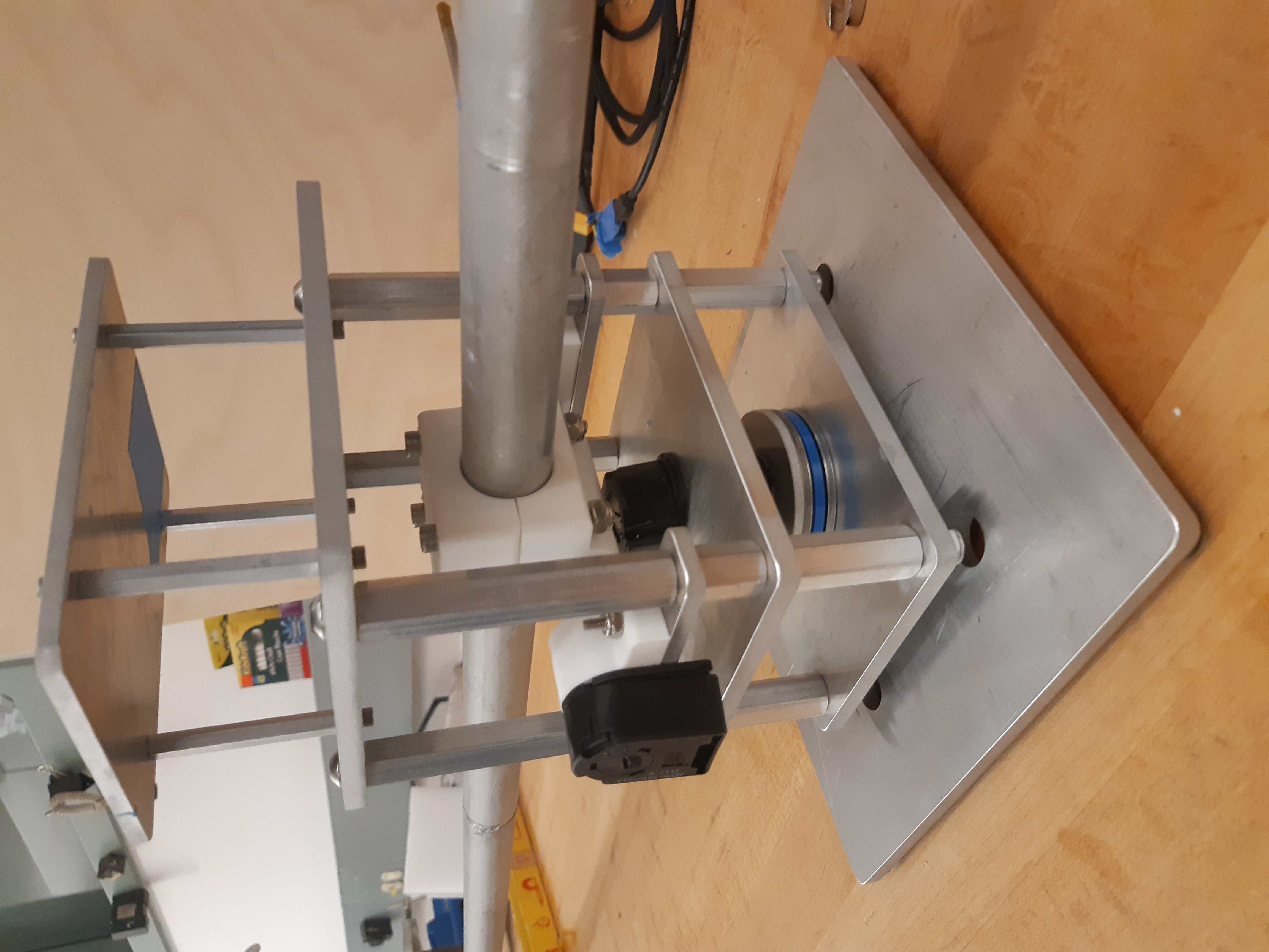
Another view of the Central Pivot Assembly
Quantity |
Part |
|---|---|
1pc |
Central Pivot Assembly(Incomplete) |
Central Pivot to Robotic Leg Adapter
1pc |
Unfinished Central Pivot Assembly |
|---|---|
1pc |
3D-printed leg adapter piece |
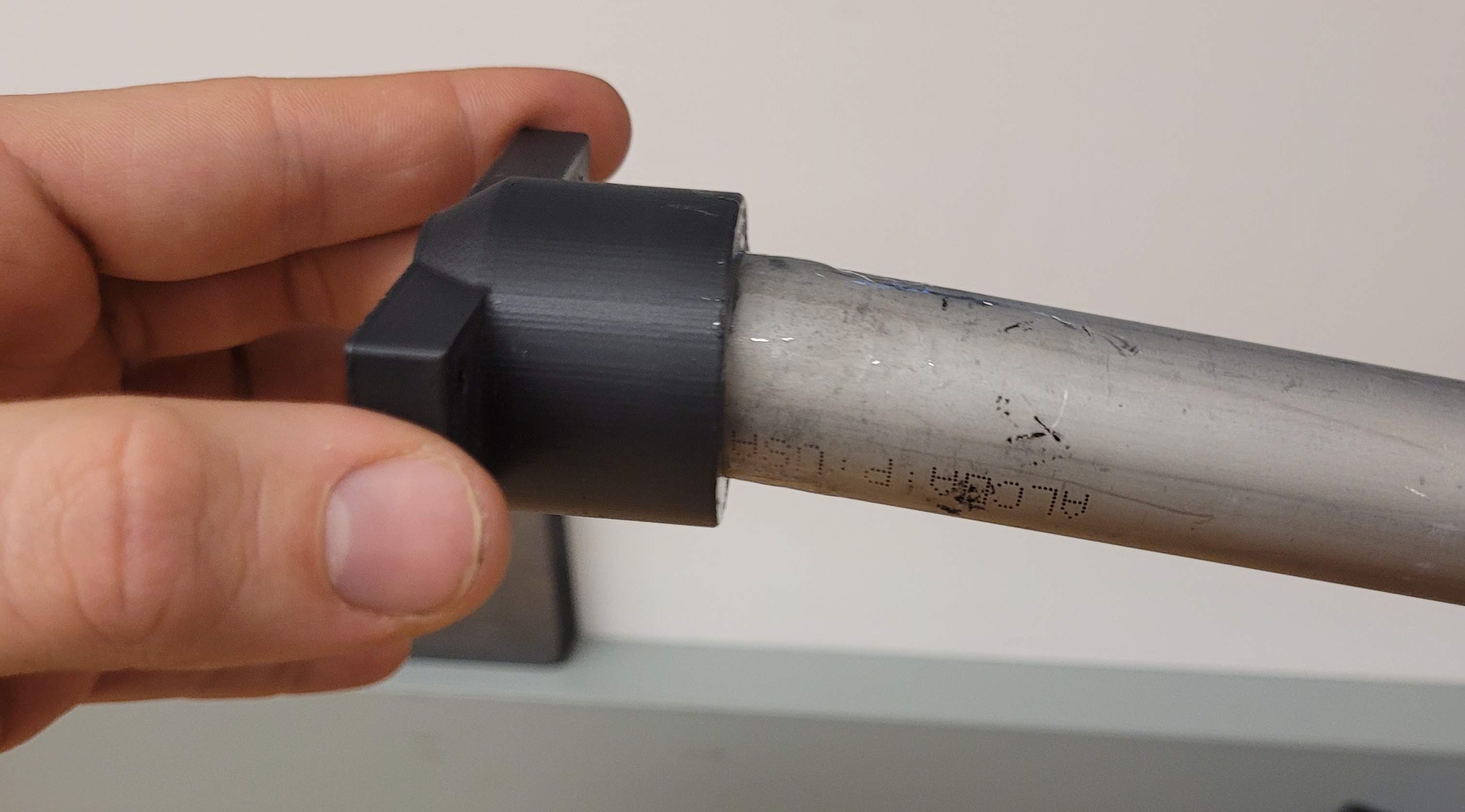
Connect the end of the Central Pivot boom to the adapter piece using epoxy.
All mechanical assembly for the Central Pivot is now complete, but there remains some wiring work to be done.
Quantity |
Part |
|---|---|
1pc |
Central Pivot Assembly(Incomplete) |
Wiring the Central Pivot Encoders
1pc |
Central Pivot Assembly(Incomplete) |
2pc |
TI LAUNCHXL microcontrollers |
2pc |
TI DRV8305 motor driver boards |
2pc |
TI LAUNCHXL holders, 3D printed |
1 spool |
5-wire cable |
20pc |
JST sockets |
4pc |
JST 5-pin housings, Male. |
Designate one of the TI LAUNCHXL microcontroller boards to control the Robotic Leg, and designate the other TI LAUNCHXL microcontroller board to control the Central Pivot. On the Robotic leg board, attach the TI DRV8305 motor driver boards, as described in the documentation.
Attach both boards to the 3D printed TI LAUNCHXL holders, and secure them in place with zipties. Attach the boards to the “Roof” and “Electronics Holder” aluminum plates.
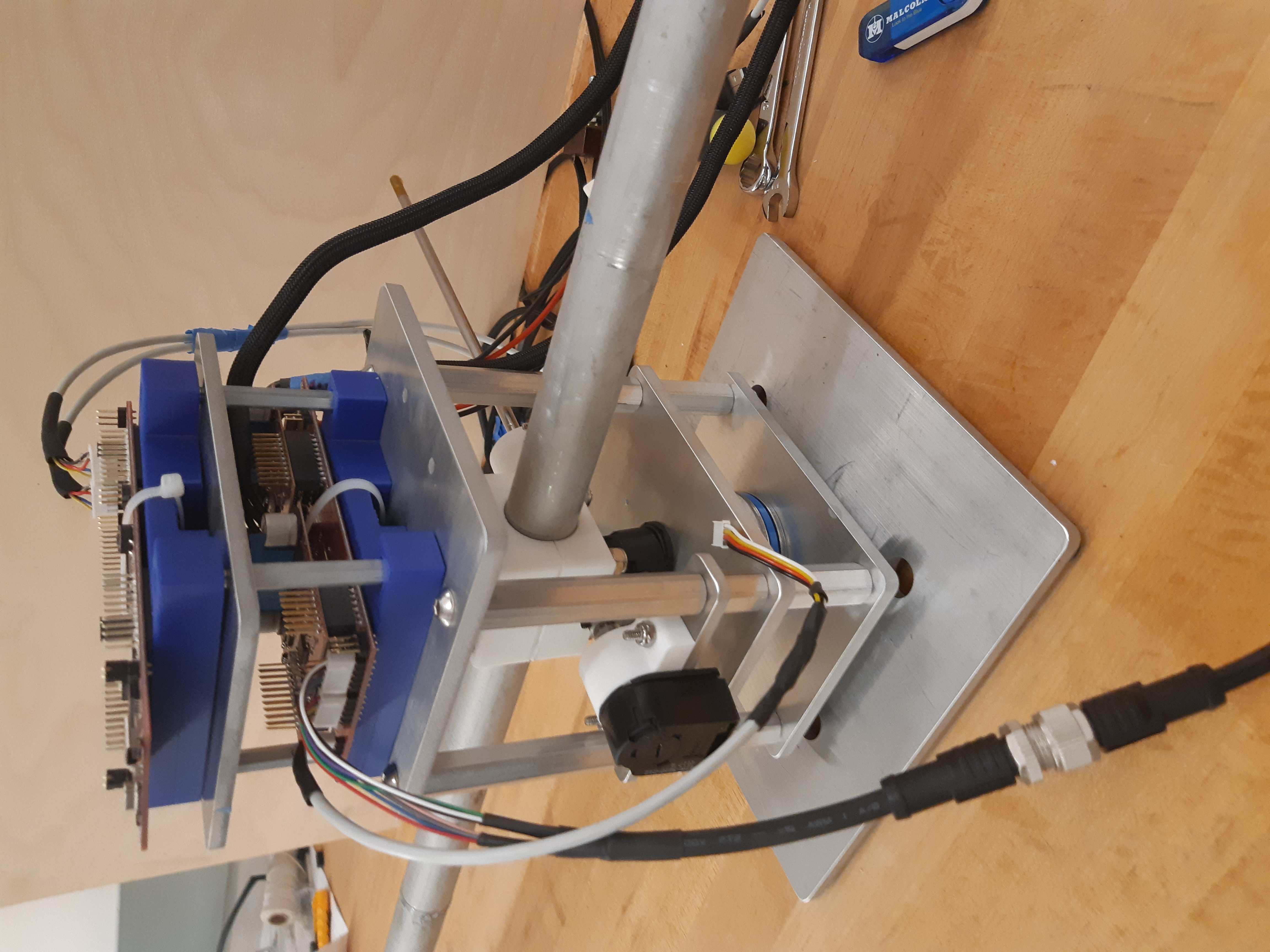
TI LAUNCHXL boards installed on the Central Pivot
Measure out 2 20cm lengths of the 5-wire cable and cut them there. At both ends, crimp JST sockets.
At both ends of each cable, connect JST 5-pin housings such that the encoder pins on the TI LAUNCHXL boards align to the encoder pins on the Central Pivot Encoders. Refer to the documentation for the TI LAUNCHXL and the documentation for the encoders for clarification:
Connect the Central Pivot TI LAUNCHXL board to the Central Pivot encoders with these new cables.
Quantity |
Part |
|---|---|
1pc |
Central Pivot Assembly(Complete) |
Conclusion
The assembly of the Central Pivot is now complete, and can be tested.